Horizontal mortar storage and transportation system
A kind of mortar and horizontal technology, which is applied in the field of mortar storage and mixing equipment for construction sites, can solve the problems that the mortar cannot be automatically conveyed out of the mortar tank, cannot meet the use requirements, and the work efficiency is not high, so as to save labor, improve labor efficiency, and use Convenient and flexible effects
- Summary
- Abstract
- Description
- Claims
- Application Information
AI Technical Summary
Problems solved by technology
Method used
Image
Examples
Embodiment 1
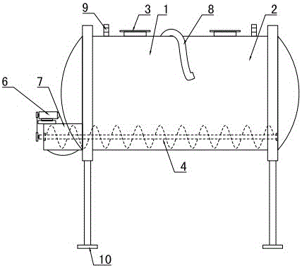
[0033] Refer to attached figure 1 : a horizontal mortar storage and transportation system, including a mortar tank, the mortar tank includes a tank body 1 installed through the lateral support of a bracket 2, and two lifting lugs 9 are installed on both sides of the upper part of the tank body 1. Support 2 adopts a height-adjustable support, including a transmission screw and a wire sleeve. The wire sleeve is vertically installed on the tank body 1 bottom, and the transmission screw extends into the inside of the wire sleeve from the bottom of the wire sleeve and is connected with the internal thread of the wire sleeve. The drive screw is locked by the locking bolt to prevent slipping. The upper end of the tank body 1 is provided with a plurality of feeding ports, and the feeding ports include two general-purpose feeding ports 3, and a mortar car feeding port 8 is arranged in the middle of the two general-purpose feeding ports 3. A stirring and conveying device 4 is horizonta...
Embodiment 2
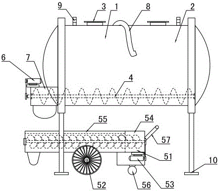
[0035] Refer to attached figure 2 : the lower part of the discharge port of the discharge passage 7 is provided with a mobile mixer truck 5, the mobile mixer truck 5 includes a horizontally placed mixing tank 51, the upper part of the mixing tank 51 is provided with a cover plate 55, and one side of the cover plate 55 is for feeding Port 54, one end of the stirring tank 51 is closed, and the other end has a discharge port. The stirring and conveying fins driven by the second motor 53 are installed in the stirring tank 51. The middle part of the lower part of the stirring tank 51 is provided with a wheel 52, and the front part of the stirring tank 51 Be provided with handrail 57, stirring tank 51 lower front ends are provided with small front wheel 56, and small front wheel 56 adopts universal wheel, can adjust direction conveniently. The rest of the settings are the same as in Example 1.
Embodiment 3
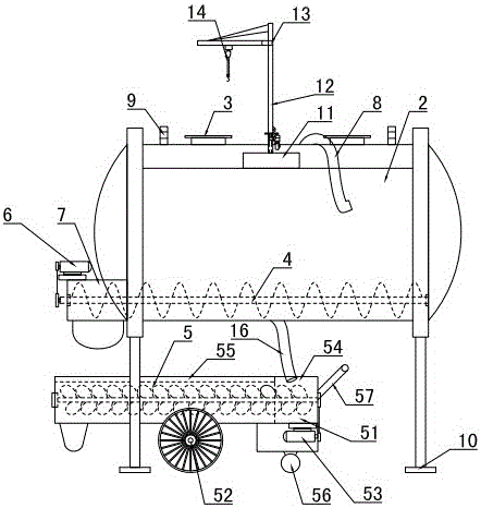
[0037] Refer to attached Figure 3-4A rotating tank crane is installed on one side of the upper part of the tank body 1, and the rotating tank crane includes a chassis 11, a vertical beam 12 and a boom 13, the chassis 11 is fixedly installed on the support frame at the upper part of the tank body 1, and the vertical beam 12 is installed at the center of the upper part of the chassis 11 , horizontal boom 13 is installed on the top of vertical beam 12, vertical beam 12 and boom 13 can realize 360 ° of rotation by motor drive, and sling 14 is installed on the boom 13. A water storage tank 15 is installed on the other side of the top of the tank body 1 , and a water outlet pipeline 16 is provided at the bottom of the water storage tank 15 . The water outlet pipeline 16 is introduced into the mixing tank 51 of the mobile mixer truck 5 . The rest of the settings are the same as in Example 2.
[0038] The first motor 6 in the above-mentioned embodiment adopts the frequency conver...
PUM
 Abstract
Description
Claims
Application Information
 - R&D
- Intellectual Property
- Life Sciences
- Materials
- Tech Scout
- Unparalleled Data Quality
- Higher Quality Content
- 60% Fewer Hallucinations
Browse by: Latest US Patents, China's latest patents, Technical Efficacy Thesaurus, Application Domain, Technology Topic, Popular Technical Reports.
© 2025 PatSnap. All rights reserved.Legal|Privacy policy|Modern Slavery Act Transparency Statement|Sitemap|About US| Contact US: help@patsnap.com


