
Tire deceleration braking device

A brake device and tire technology, applied to vehicle parts, transportation and packaging, brakes, etc., can solve the problems of waste, easily damaged brakes, irregular brake replacement, etc., and achieve the effect of reasonable structure, precise structure and convenient production

Inactive Publication Date: 2015-04-22
毛开元
View PDF5 Cites 0 Cited by
  • Summary
  • Abstract
  • Description
  • Claims
  • Application Information

AI Technical Summary

Problems solved by technology

[0002] Tires are installed on the large instruments and equipment used in the existing factories, which is convenient for the movement of the instruments and equipment. The tire brakes on the instruments and equipment are inconvenient to use and difficult for workers to operate. It is easy to damage the brakes, and the brakes need to be replaced irregularly, causing unnecessary waste

Method used


Image

  • Tire deceleration braking device
  • Tire deceleration braking device
  • Tire deceleration braking device

Examples


Embodiment Construction

[0018] Below in conjunction with embodiment, further illustrate the present invention.

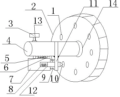
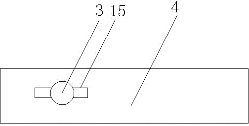
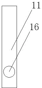
[0019] see figure 1 , the present invention comprises a tire 2 and a wheel shaft 4, the tire 2 is provided with a groove 1, the wheel shaft 4 is provided with a push block 3 capable of moving up and down, and one side of the wheel shaft 4 is provided with a fixed shaft 11, so The lower side of the fixed shaft 11 is passed by the deceleration pin 10, the lower end of the axle 4 is provided with a lower ratchet 6, the lower end of the axle 4 is provided with a sleeve 7, and the upper end of the sleeve 7 is provided with a The upper ratchet 5 matched with the lower ratchet 6, one end of the sleeve 7 is provided with a notch 12, the inner spring 8 is arranged in the notch 12, and one end of the inner spring 8 is connected in the notch 12, The other end is connected with the speed reduction pin 10 .

[0020] The sleeve 7 is connected to the fixed shaft 11 through an outer spring.

[0021] Th...


PUM


Abstract

The invention provides a tire deceleration braking device. The tire deceleration braking device comprises a tire and a wheel axle. The tire deceleration braking device is characterized in that the tire is provided with a groove; the wheel axle is provided with a pushing block which can move vertically; one side of the wheel axle is provided with a fixing shaft; a deceleration pin penetrates the lower side of the fixing shaft; the lower end of the wheel axle is provided with a lower ratchet; the lower end of the wheel axle is provided with a sleeve; the upper end of the sleeve is provided with an upper ratchet which is matched with the lower ratchet; one end of the sleeve is provided with a notch; an inner spring is arranged in the notch; one end of the inner spring is connected into the notch and the other end of the inner spring is connected with the deceleration pin.

Description

technical field [0001] The invention relates to the field of tires, in particular to a tire deceleration brake device. Background technique [0002] Tires are installed on the large instruments and equipment used in the existing factories, which is convenient for the movement of the instruments and equipment. The tire brakes on the instruments and equipment are inconvenient to use and difficult for workers to operate. It is easy to damage the brakes, and the brakes need to be replaced irregularly, causing unnecessary waste. Invention content: [0003] The technical problem to be solved by the present invention is to provide a tire deceleration and braking device to realize stepless tire braking. [0004] The present invention adopts following technical means to realize the object of the invention: [0005] A tire deceleration braking device, comprising a tire and a wheel shaft, characterized in that: the tire is provided with a groove, the wheel shaft is provided with a ...

Claims


Application Information

Patent Timeline
IPC IPC(8): B60T1/06
CPCB60T1/06
Inventor 尤晓明王显涛李洋迟文泉邓世海
Owner 毛开元
Learn More