
Automatic pipe bending machine

A pipe bending machine, automatic technology, applied in the direction of metal processing equipment, feeding device, positioning device, etc., can solve the problems of difficult control of bending degree, low working efficiency of bending machine, etc., and achieve the effect of improving service life

Inactive Publication Date: 2015-04-22
WUHU HENGMEI ELECTRIC HEATING APPLIANCE
View PDF6 Cites 15 Cited by
  • Summary
  • Abstract
  • Description
  • Claims
  • Application Information

AI Technical Summary

Problems solved by technology

[0003] In view of the problems existing in the above-mentioned prior art, the object of the present invention is to provide an automatic bending machine for bending air-conditioning pipes, which can bend the air-conditioning pipes through the rotation between the fixed column and the bending column, and through The steel pipe conveying track and the clamping block are used to load and clamp the air-conditioning pipe, and automatically perform the bending work, which solves the problem of low working efficiency and difficult control of the bending degree of the bending machine

Method used


Image

  • Automatic pipe bending machine
  • Automatic pipe bending machine

Examples


Embodiment Construction

[0013] In order to deepen the understanding of the present invention, the present invention will be further described below in conjunction with examples, which are only used to explain the present invention and do not constitute a limitation to the protection scope of the present invention.

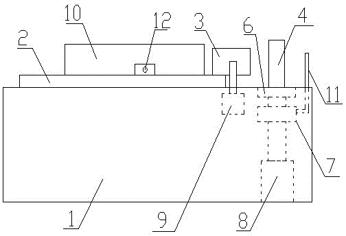
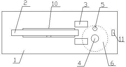
[0014] Such as figure 1 , 2 As shown, this embodiment provides an automatic pipe bending machine, including a fuselage 1, a steel pipe conveying track 2 is arranged on the fuselage 1, and a clamping block 3 is arranged at the right end of the steel pipe conveying track 2, and the clamp The right side of the tight block 3 is provided with a fixed column 4, the rear end of the fixed column 4 is provided with a bending column 5, the bottom of the fixed column 4 is provided with a rotating disc 6, and the fixed column 4 is arranged at the center of the rotating disc 6, The bending column 5 is arranged on the edge of the rotating disc 6, the rotating motor 7 is arranged at the bottom of the r...


PUM


Abstract

The invention provides an automatic pipe bending machine. The automatic pipe bending machine comprises a machine body, wherein a steel tube conveying rail is arranged on the machine body, a clamping block is arranged at the right end of the steel tube conveying rail, a fixing pillar is arranged on the right side of the clamping block, a bending pillar is arranged at the rear end of the fixing pillar, a rotation plate is arranged at the bottom of the fixing pillar, the fixing pillar is arranged at the center of the rotation plate, the bending pillar is arranged on the edge of the rotation plate, a rotation motor is arranged at the bottom of the rotation plate, the rotation plate is driven by the rotation motor to rotate, and the right end of the steel tube conveying rail is located between the fixing pillar and the bending pillar. The automatic pipe bending machine bends air conditioning pipes through rotation between the fixing pillar and the bending pillar, and loads and clamps the air conditioning pipes through the steel tube conveying rail and the clamping block, automatically performs bending work, retracts the fixing pillar, the bending pillar, the rotation plate and the rotation motor into the machine body when the fixing pillar, the bending pillar, the rotation plate and the rotation motor are not needed to work by arranging a lifting air cylinder, and prevents the fixing pillar, the bending pillar, the rotation plate and the rotation motor from being polluted by dust and abraded due to inattention of workers, and therefore use life of the automatic pipe bending machine is prolonged.

Description

technical field [0001] The invention relates to the field of air-conditioning pipe manufacturing, in particular to an automatic bending machine for bending air-conditioning pipes. Background technique [0002] At present, when manufacturing air-conditioning pipes, it is necessary to bend the air-conditioning pipes into bends suitable for the size of the air conditioner, so as to facilitate installation in the air conditioner. At present, for the bending of air-conditioning pipes, the material feeding and the control of the bending cylinder are usually carried out manually. Feeding is troublesome, and it is difficult to control the bending degree when the bending cylinder is bent. Therefore, it is particularly important to solve the problem of low working efficiency of the bending machine and difficulty in controlling the bending degree. Contents of the invention [0003] In view of the problems existing in the above-mentioned prior art, the object of the present inventio...

Claims


Application Information

Patent Timeline
Patent Type & Authority Applications(China)
IPC IPC(8): B21D7/024B21D43/00B21D43/02
CPCB21D7/024B21D43/003B21D43/02
Inventor 张怀国
Owner WUHU HENGMEI ELECTRIC HEATING APPLIANCE
Learn More