A Thermally Coupled Jet Parallel Flow Tower with Heat Exchange Trays

A heat exchange tray and thermal coupling technology, applied in fractionation and other directions, can solve the problems of small internal thermal coupling heat transfer area, difficult popularization and application, high cost, easy installation, maintenance and production operation, large economic benefits and application prospects , the effect of saving operating costs

Active Publication Date: 2016-06-22
SHIJIAZHUANG GONGDA CHEM EQUIP
View PDF7 Cites 0 Cited by
  • Summary
  • Abstract
  • Description
  • Claims
  • Application Information

AI Technical Summary

Problems solved by technology

In 2005, the United Kingdom developed an internal heat-coupled rectification column with internal heat transfer on the tray, and the European Union developed a heat transfer panel (Heat transfer panel, referred to as HTP) type internal heat-coupled rectification column. However, due to the thermal coupling inside the column The heat transfer area is small, so no application progress has been made
From 1995 to 2007, Japan successively developed concentric cylindrical and multi-concentric cylindrical bundled thermally coupled rectification towers; however, the structure of concentric cylindrical thermally coupled rectification towers is relatively simple, but the original internal thermal coupling has not yet been solved. The heat transfer area is small. Although the multi-concentric cylinder bundled internal thermally coupled distillation tower has a larger heat transfer area, its structure is complex and the cost is high, so it is difficult to popularize and apply in practice.
[0004] In 2009, the Chinese patent CN200910087709.9 designed an internal thermally coupled distillation column. The thermal coupling between the rectifying section and the stripping section was realized through three external heat exchangers, and the top of the rectifying section and the Heat exchange between the tops of the stripping section, thereby realizing the operation of the internal thermally coupled distillation column without external heat recovery; however, the internal thermally coupled distillation column includes four external heat exchangers and two tower bodies, and the equipment volume is large ,high cost
However, the heat of the liquid co-current composite tower is provided by the reboiler at the bottom of the tower, which has high energy consumption and low heat utilization rate. In addition, in order to achieve a better rectification effect, the height of the tower is usually high, and the installation and construction are difficult. Difficult to maintain and overhaul

Method used


Image

  • A Thermally Coupled Jet Parallel Flow Tower with Heat Exchange Trays
  • A Thermally Coupled Jet Parallel Flow Tower with Heat Exchange Trays
  • A Thermally Coupled Jet Parallel Flow Tower with Heat Exchange Trays

Examples


Embodiment Construction

[0025] Below in conjunction with embodiment and accompanying drawing, the present invention is described in further detail:

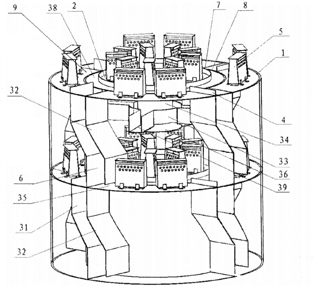
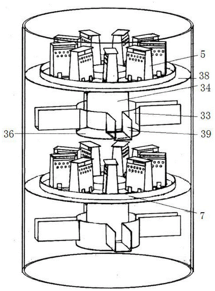
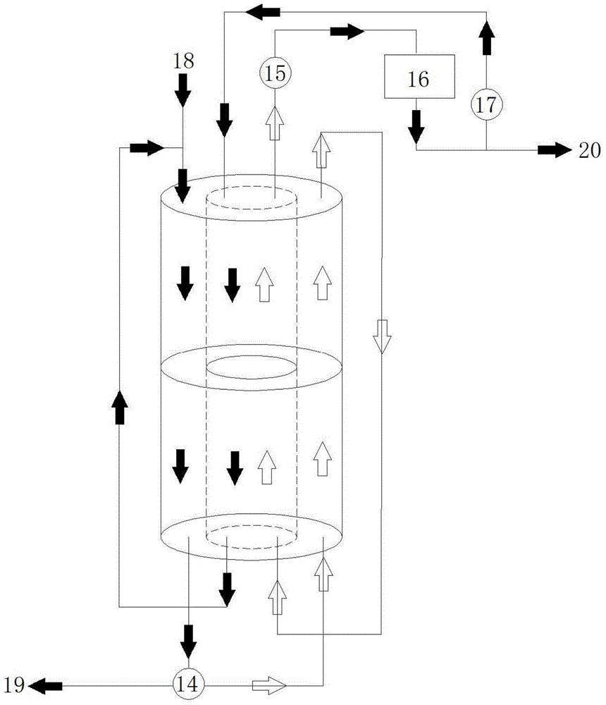
[0026] A thermally coupled jet parallel flow tower, comprising a cylindrical tower body 1; the tower body 1 includes a cylindrical inner tower 8 and an annular outer tower 9, the inner tower 8 is set in the outer tower 9; the inner tower 8 and the outer tower 9 The space is separated into a rectification section and a stripping section by the outer wall of the inner tower 8. When the inner tower 8 is the rectification section, the outer tower 9 is the stripping section; when the inner tower 8 is the stripping section, the outer tower 9 is the rectification section. A reboiler 14 for providing heat to the tower body is arranged at the bottom of the tower, and the reboiler 14 is connected with the bottom of the stripping section; a condenser 15 and a reflux pump 17 are arranged at the top of the rectifying section.

[0027] The structure of the outer tow...


PUM


Abstract

The invention discloses a thermal coupling jet concurrent flow tower with heat exchange tower plates. The thermal coupling jet concurrent flow tower comprises a tower body and a plurality of layers of continuous mass transfer tower plates. The tower body comprises an inner tower and an outer tower. Each layer of continuous mass transfer tower plate comprises a tower plate body with air rising holes, a cover hood and a liquid falling system. The portion between the inner tower and the outer tower is partitioned by the outer wall of the inner tower to form a rectifying section and a stripping section. The tower plates of the rectifying section are heat exchange tower plates communicated with the stripping section through heat exchange inlets and heat exchange outlets. The heat exchange inlets and the heat exchange outlets of the heat exchange tower plates are located in a mass transfer region outside the liquid falling system of the stripping section. According to the tower, the temperature difference of the rectifying section and the stripping section are effectively utilized to conduct heat exchange and heat recycling at the tower wall of the inner tower, the heat exchange area of the heat exchange tower plates is increased, the heat dissipation amount is effectively reduced, the heat transfer from the stripping section to the rectifying section is enhanced, the purposes of saving energy and reducing consumption are achieved, and thus the thermal coupling jet concurrent flow tower has greater economical benefits and wider application prospects.

Description

technical field [0001] The invention relates to a gas-liquid mass transfer device, in particular to a heat-coupled jet parallel flow tower with heat exchange trays, which is used for mass transfer processes in the fields of chemical industry, oil refining, petrochemical, environmental protection and the like. Background technique [0002] In the petrochemical process, the rectification process is one of the most widely used unit operations, and it is also the operating unit with the largest energy consumption in the petrochemical field. In a traditional distillation column, the heat introduced into the reboiler of the distillation column is discharged from the condenser after passing through the distillation column. Most of the energy is lost in the pressure drop of the column and the temperature difference through the heat exchanger, and only part of it is The energy is used to reduce the entropy of the product of the rectification tower, and its thermodynamic efficiency is...

Claims


Application Information

Patent Timeline
Patent Type & Authority Patents(China)
IPC IPC(8): B01D3/14B01D3/32
Inventor 张继军陈学青王静洁姚红果
Owner SHIJIAZHUANG GONGDA CHEM EQUIP
Why Eureka
Try Eureka