
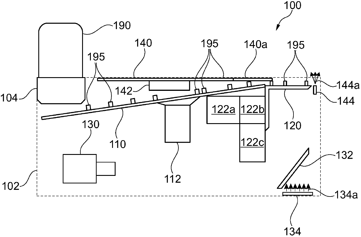
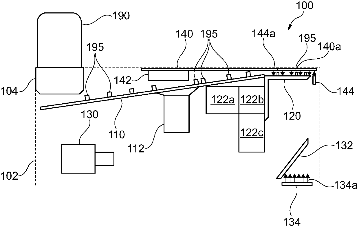
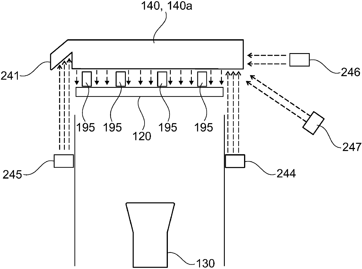
Vibration feeds the component and detects it from below with the integrated camera

A camera and component technology, applied in the direction of electrical components, electrical components, electrical solid devices, etc., can solve the problem that the supply or pickup position cannot be accurately defined, and achieve the effect of a simple and effective method, easy vibration conveying, and easy component picking.

Active Publication Date: 2018-02-02
ASM ASSEMBLY SYST GMBH & CO
View PDF5 Cites 0 Cited by
  • Summary
  • Abstract
  • Description
  • Claims
  • Application Information

AI Technical Summary

Problems solved by technology

But in this known vibrating conveyor, the supply or pick-up position cannot be precisely defined for each element

Method used


Image

  • Vibration feeds the component and detects it from below with the integrated camera
  • Vibration feeds the component and detects it from below with the integrated camera
  • Vibration feeds the component and detects it from below with the integrated camera

Examples


Embodiment Construction

[0148] It should be noted that in the following detailed description, features or components of different embodiments (which are identical or at least functionally identical to corresponding features or components of other embodiments) are generally provided with the same reference signs or different reference signs, and the different Reference signs differ from those of identical or at least functionally identical features or components only by their first letter. In order to avoid unnecessary repetition, features or components which have already been explained with reference to the exemplary embodiments described above will not be explained in more detail below.

[0149] Furthermore, it should be pointed out that the embodiments described below are only selected from among the possible embodiments of the invention. In particular, it is possible to combine features of the individual exemplary embodiments with one another in a suitable manner, so that a multiplicity of differe...


PUM


Abstract

The invention describes a component supply apparatus for providing separated elements (195, 595a, 595b). The component supply apparatus (100, 200, 600, 700) has (a) a vibrating conveyor (122a, 122b, 122c, 622a, 622b), (b) a supply element (120, 320, 420) with a supply area, wherein the vibrating conveyor (122a, 122b, 122c, 622a, 622b) is configured to enable the supply element (120, 320, 420) to vibrate so that the separated elements (195, 595a, 595b) can be conveyed into the supply area from an upper surface of the supply element (120, 320, 420), and a camera (130, 630) which is arranged below the supply element (120, 320, 420), wherein the supply element (120, 320, 420) is optically transparent at least in the region of the supply area is, so that elements (195, 595a, 595b) which have been conveyed in the supply area can pass from the bottom of the supply element (120, 320, 420) and be detectable by the camera (130,630). Additionally, a method for providing the separated element (195, 595a, 595b) and an assembling system (750) are also described. The assembling system has the above component supply apparatus (100, 200, 600, 700).

Description

technical field [0001] The invention relates to the supply of separated electronic components in a supply zone for further processing of the supplied discrete electronic components. In particular, the invention relates to a component supply device and a method for supplying separate components and in particular separate electronic components for the purpose of automatic assembly with component carriers in an automatic assembly machine. Furthermore, the invention relates to an assembly system having an automatic assembly machine and a component supply device of the above-mentioned type. Background technique [0002] The process of supplying the components to be processed to a pick or place position when the component carrier is mechanically assembled with the (electronic) component is a typical assembly procedure in an automatic assembly machine. The supply of components takes place here in such a way that the components have a precisely defined spatial orientation so that t...

Claims


Application Information

Patent Timeline
Patent Type & Authority Patents(China)
IPC IPC(8): H05K13/02
CPCH05K13/0434H01L2224/95H01L2924/12044H05K13/028H05K13/081H01L2924/00
Inventor 斯特凡·马格安德烈亚斯·佐勒卡尔·海因茨·贝施哈拉尔德·施坦兹尔诺伯特·海尔曼克里斯托夫·菲舍尔
Owner ASM ASSEMBLY SYST GMBH & CO
Learn More