Optical signal processing method, optical module and optical line terminal

An optical line terminal, optical signal technology, applied in the field of optical communication

Inactive Publication Date: 2015-04-15
ZTE CORP
View PDF5 Cites 10 Cited by
  • Summary
  • Abstract
  • Description
  • Claims
  • Application Information

AI Technical Summary

Problems solved by technology

[0004] The technical problem to be solved by the present invention is to provide a processing method for optical s

Method used


Image

  • Optical signal processing method, optical module and optical line terminal
  • Optical signal processing method, optical module and optical line terminal
  • Optical signal processing method, optical module and optical line terminal

Examples


Embodiment Construction

[0033] In order to make the purpose, technical solution and advantages of the present invention more clear, the embodiments of the present invention will be described in detail below in conjunction with the accompanying drawings. It should be noted that, in the case of no conflict, the embodiments in the present application and the features in the embodiments can be combined arbitrarily with each other.

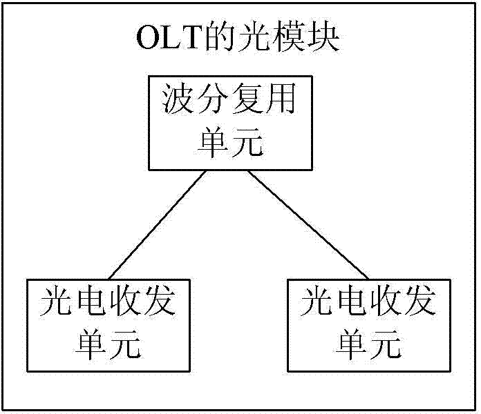
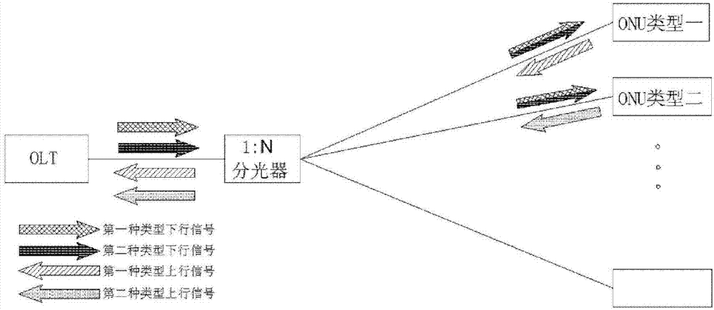
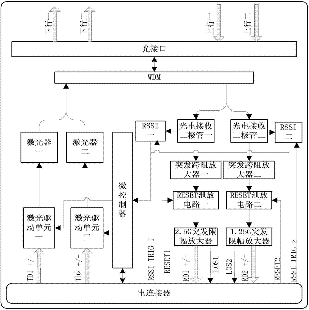
[0034] figure 1 It is a schematic diagram of the optical module of the OLT of the embodiment of the present invention, such as figure 1 As shown, the optical module of this embodiment includes: two photoelectric transceiver units and a wavelength division multiplexing unit,

[0035] The photoelectric transceiver unit is used to generate a downlink optical signal of a corresponding rate and wavelength according to the electrical signal, and then output it to the wavelength division multiplexing unit; it is used to receive the corresponding rate of the burst mode output by the...


PUM


Abstract

An optical signal processing method, optical module, OLT optical signal processing method and OLT are disclosed in the embodiments of the present invention. The optical module comprises two photoelectric transceiver units and a wavelength division multiplexer unit. The photoelectric transceiver units are configured to: generate, according to an electric signal, a downlink optical signal with a corresponding rate and wavelength, and then output the downlink optical signal to the wavelength division multiplexer unit; and receive an uplink optical signal with a rate and wavelength corresponding to a burst mode from the wavelength division multiplexer unit, and convert the uplink optical signal into an electric signal. The wavelength division multiplexer unit is configured to: after receiving the downlink optical signals from the two photoelectric transceiver units, wavelength division multiplex the downlink optical signals and then output the outcome; receive the uplink optical signal, de-multiplex the uplink optical signal to obtain uplink optical signals with different rates and wavelengths, and output the uplink optical signals to the corresponding photoelectric transceiver units respectively.

Description

technical field [0001] The present invention relates to the technical field of optical communication, in particular to an optical signal processing method and an OLT (Optical Line Terminal, optical line terminal). Background technique [0002] With the rapid development of optical fiber communication technology and the promotion and popularization of optical fiber access technology, people's demand for bandwidth continues to increase, making the current commercialized technology gradually unable to meet the growing demand for broadband services. The technology that provides higher bandwidth becomes the solution of the next generation broadband access network. [0003] For products that have already been used in a large number of commercial applications, the technical solutions are mature and stable. Considering the cost and maintenance, the application of higher bandwidth solutions must also consider the smooth upgrade of the system. The problem of smooth upgrade of the sys...

Claims


Application Information

Patent Timeline
IPC IPC(8): H04Q11/00H04B10/40H04J14/02
CPCH04J14/02H04B10/25H04J14/0242H04B10/27H04B10/503H04J14/0227
Inventor 匡国华付志明李锟陈雷朱松林
Owner ZTE CORP
Why Eureka
Try Eureka