Optical line terminal, optical transceiving module, system and optical fiber detection method

An optical line terminal, optical transceiver module technology, applied in the field of optical communication, can solve problems such as smooth upgrade of optical transceiver modules that cannot achieve OTDR, and major changes in network architecture.

Active Publication Date: 2017-03-15
HUAWEI TECH CO LTD
View PDF4 Cites 5 Cited by
  • Summary
  • Abstract
  • Description
  • Claims
  • Application Information

AI Technical Summary

Problems solved by technology

However, the definition of the pins of the modified optical transceiver module has been inconsistent with the standard, so that the optical transceiver module that supports the OTDR test function must be used in conjunction with the single board that supports the OTDR function. Only the original optical transceiver module can realize the test function of OTDR, which leads to too much change to the existing network architecture, and it is impossible to realize the smooth upgrade of the optical transceiver module of OTDR

Method used


Image

  • Optical line terminal, optical transceiving module, system and optical fiber detection method
  • Optical line terminal, optical transceiving module, system and optical fiber detection method
  • Optical line terminal, optical transceiving module, system and optical fiber detection method

Examples


Embodiment Construction

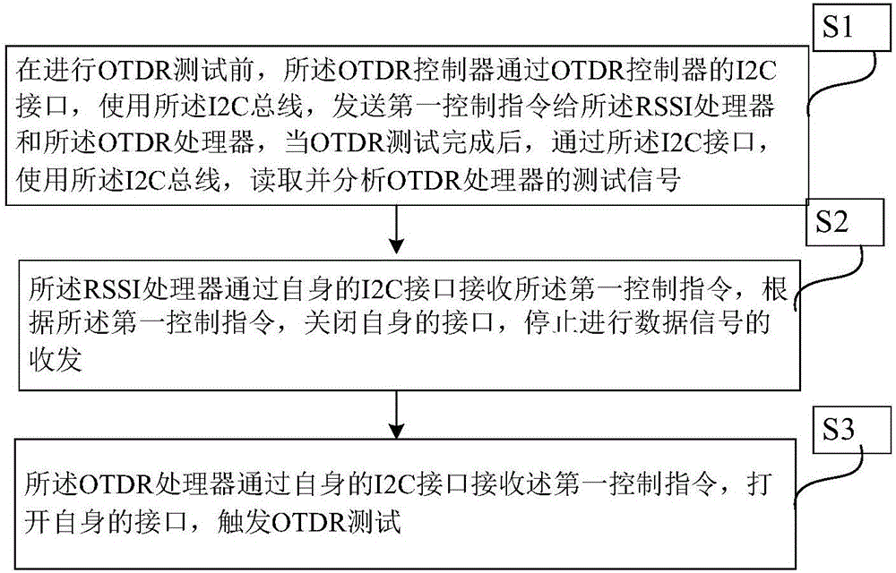
[0027] The optical transceiver module and optical fiber detection method provided by the present application will be described in detail below in conjunction with specific embodiments.

[0028] The optical transceiver module provided in this application can be applied to point-to-multipoint optical fiber networks such as passive optical network systems. see figure 1 , which is a schematic structural diagram of a passive optical network system. The passive optical network system 100 includes at least one optical line terminal 110 , a plurality of optical network units 120 and an optical distribution network 130 . The optical line terminal 110 is connected to the plurality of optical network units 120 through the optical distribution network 130 . Wherein, the direction from the OLT 110 to the ONU 120 is defined as the downlink direction, and the direction from the ONU 120 to the OLU 110 is defined as the uplink direction.

[0029] The passive optical network system 100 may b...


PUM


Abstract

The invention provides an optical fiber detection method. Control is implemented on an OTDR processor by reusing an I2C bus connection between an I2C interface of an RSSI controller and an I2C interface of an RSSI processor on a board of an optical line terminal, so as to implement faulty location for an optical fiber trunk and a distributed optical fiber of an optical fiber network, as well as line analysis and faulty responsibility determination and demarcation for optical fiber branches and optical network units, instead of modifying an original pin of an optical transceiving module on the optical line terminal, so that the board of the optical line terminal supporting OTDR can support an original optical transceiving module supporting an OTDR test and support an original optical transceiving module not-supporting the OTDR test simultaneously, thereby implementing smooth upgrading of the optical transceiving module of the OTDR.

Description

technical field [0001] The present application relates to optical communication technology, and in particular, relates to an optical line terminal, an optical transceiver module, a system, and an optical fiber detection method. Background technique [0002] With the continuous increase of users' demand for bandwidth, the traditional copper broadband access system is increasingly facing bandwidth bottlenecks; at the same time, the optical fiber communication technology with huge bandwidth capacity is becoming more and more mature, and the application cost is decreasing year by year. The optical fiber access network has become the next A strong competitor of the first-generation broadband access network, especially the passive optical network is more competitive. [0003] Generally speaking, a passive optical network system includes an optical line terminal (Optical Line Terminal, OLT) located in the central office, a plurality of optical network units (Optical Network Unit, O...

Claims


Application Information

Patent Timeline
Patent Type & Authority Applications(China)
IPC IPC(8): H04B10/071H04B10/272
CPCH04B10/071H04B10/272
Inventor 殷锦蓉杨素林
Owner HUAWEI TECH CO LTD
Why Eureka
Try Eureka