Design method for free curved surface imaging system

An imaging system and design method technology, applied in computer-aided design, constraint-based CAD, optics, etc., can solve problems such as design difficulties in large field of view systems, achieve broad application prospects, development potential, and high fitting accuracy

Active Publication Date: 2015-04-15
TSINGHUA UNIV +1
View PDF6 Cites 9 Cited by
  • Summary
  • Abstract
  • Description
  • Claims
  • Application Information

AI Technical Summary

Problems solved by technology

But this method is mainly suitable for small field of view systems, and it is very difficult to design for large field of view systems

Method used


Image

  • Design method for free curved surface imaging system
  • Design method for free curved surface imaging system
  • Design method for free curved surface imaging system

Examples


Embodiment Construction

[0019] The technical solution of the present invention will be further described in detail below according to the drawings in the description and in combination with specific embodiments.

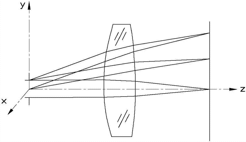
[0020] In the present invention, the free-form surface imaging system includes a lens and an interpupillary distance, and the lens has two opposite curved surfaces in the incident direction of light. The light beam enters the free-form surface imaging system from the pupil, the curved surface close to the pupil is the front surface of the lens, and the curved surface relatively far from the through hole is the rear surface of the lens. A light beam exiting the pupil is incident on the front surface of the lens and exits from the rear surface of the lens.

[0021] see figure 1 , the design method of the freeform surface imaging system provided by the first embodiment of the present invention includes the following steps:

[0022] Step S10, establishing an initial structural model of the fr...


PUM


Abstract

A design method of freeform imaging lens with a wide linear field-of-view (FOV) is provided. A initial freeform imaging lens is developed, and the initial freeform imaging lens includes a first lens surface and an entrance pupil spaced from each other, wherein the FOV of the system 2ω (±ω) is divided into 2k+1 sampling fields with equal interval Δω between each two adjacent sampling fields. Each two adjacent sampling fields are taken as one group. Two constraints are employed to calculate the plurality of data points of the first lens surface to obtain a front surface of the freeform imaging lens. The data points are calculated based on Snell's law, and a curve is obtained through the data points. A back surface is added to approximately keep the previous outgoing direction of rays from the front surface.

Description

technical field [0001] The invention relates to the field of optical design, in particular to a design method of a free-form surface imaging system. Background technique [0002] Free-form surfaces refer to non-traditional surfaces that cannot be represented by spherical or aspherical coefficients. They are usually non-rotational symmetric, flexible in structure, and have many variables, which provide more degrees of freedom for optical design and can greatly reduce the aberration of the optical system. , to reduce the volume, weight and number of lenses of the system. [0003] In recent decades, freeform surfaces have been successfully used in non-imaging fields, especially in lighting. In the field of modern imaging, the field of view and aperture of the optical system are larger, which puts forward higher requirements for image quality, volume, and weight. At the same time, the system structure is more complex, resulting in various special aberrations. With its many var...

Claims


Application Information

Patent Timeline
Patent Type & Authority Applications(China)
IPC IPC(8): G02B27/00
CPCG06F17/50G02B27/0012G02B3/02G06F30/00G06F2111/04
Inventor 朱钧杨通金国藩范守善
Owner TSINGHUA UNIV
Why Eureka
Try Eureka