
Submersible electric pump

A technology for submersible electric pumps and motor shafts, applied to pumps, pump devices, pump components, etc., can solve the problems of increased overall weight of motor submersible electric pumps, reduced motor efficiency and power factor, and decreased overall efficiency of submersible electric pumps. Increased efficiency, reduced diffusion angle, and ease of disassembly

Inactive Publication Date: 2015-04-15
HEFEI HENGDAJIANGHAI PUMP IND CO LTD
View PDF11 Cites 3 Cited by
  • Summary
  • Abstract
  • Description
  • Claims
  • Application Information

AI Technical Summary

Problems solved by technology

However, a low-speed motor is much larger than a high-speed motor. The lower the speed, the larger the volume and the larger the outer diameter of the motor. The increase in the outer diameter of the motor leads to the bulb ratio of the submersible pump (motor outer diameter / impeller Diameter) increases, the divergence angle of the guide vane body increases, and the streamline of the guide vane is deformed, resulting in a decrease in the overall efficiency of the submersible pump
[0006] If the direct-connected large-scale submersible pump meets the requirements of large flow and little head change by reducing the speed, there are still the following disadvantages: (1) The decrease of the motor speed leads to the decrease of the motor efficiency and power factor; (2) The decrease of the motor speed, The increase in volume leads to an increase in production costs; (3) The increase in the volume of the motor leads to an increase in the overall weight of the submersible pump

Method used


Image

  • Submersible electric pump
  • Submersible electric pump
  • Submersible electric pump

Examples


Embodiment Construction

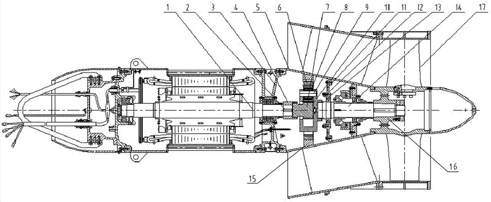
[0026] see figure 1 , figure 2 , a submersible electric pump, comprising a motor and a guide vane body 5; one end of the motor shaft 1 of the motor extends outside the end cover 3, and extends into the guide vane body 5, and is correspondingly connected to the impeller hub located in the impeller body 16. The guide vane body 5 is provided with a planetary gear reduction mechanism, and one end of the motor shaft 1 extending outside the end cover 3 is connected to the axle of the sun gear 7 of the planetary gear reduction mechanism through a coupling.

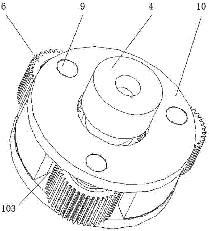
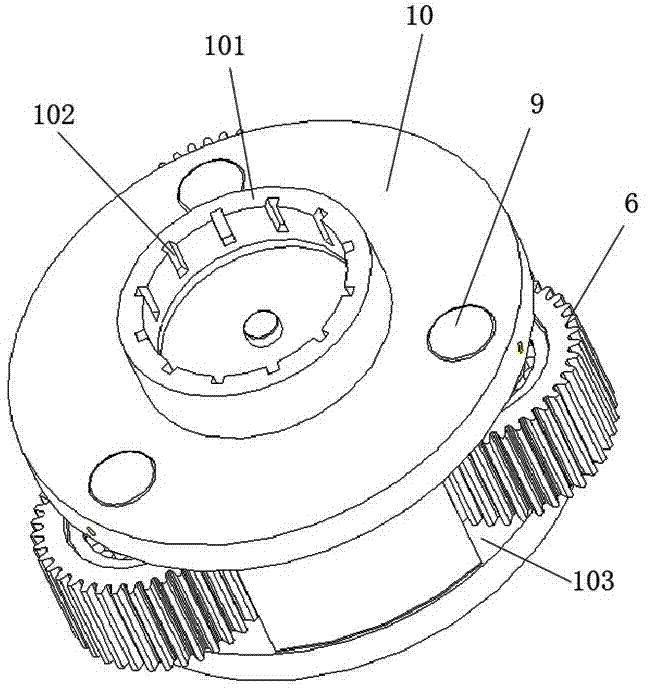
[0027] see image 3 , Figure 4 , Figure 5 , the planetary gear reduction mechanism is composed of a gear box 10, a ring gear 15, a sun gear system, and a planetary gear 6; 15 is coaxially provided with a gear box 10 in the shape of a circular box, and a sun gear system is arranged axially in the middle of the gear box 10; The wheel shaft extends out of the second sun gear 701 on the end of the gearbox 10, and the second s...


PUM


Abstract

A submersible electric pump comprises a motor, a guide vane body and an impeller body, wherein one end of a motor shaft of the motor stretches out of an end cover, stretches into the guide vane body and is correspondingly connected with an impeller hub located in the impeller body; a planetary gear speed reducing mechanism is arranged in the guide vane body; one end of the motor shaft, which stretches out of the end cover, is connected with a wheel shaft of a sun wheel of the planetary gear speed reducing mechanism by a shaft coupler. The planetary gear speed reducing mechanism is composed of a gear box, a gear ring, a sun wheel system and planetary wheels; the gear ring is arranged along the radial direction of an inner wall of a cavity of the guide vane body; the gear box with a round box shape is coaxially arranged in the gear ring and the sun wheel system is coaxially arranged in the middle of the gear box; the sun wheel system is composed of a sun wheel arranged in the gear box and a second sun wheel arranged at the stretching-out end part of the wheel shaft of the sun wheel; the second sun wheel is an input end and is connected with the motor shaft; the sun wheel is an output end; more than two planetary wheels are engaged on the sun wheel; the planetary wheels are exposed out of corresponding openings in the side wall of the gear box and are engaged with the gear ring.

Description

technical field [0001] The invention belongs to the technical field of submersible electric pumps, and in particular relates to a submersible electric pump provided with a deceleration mechanism. Background technique [0002] At present, medium and small submersible pumps with an impeller diameter less than φ1400mm mostly adopt a direct connection structure, that is, the impeller of the submersible pump and the motor driving the impeller share the same shaft, and the rotation of the motor shaft directly drives the impeller to rotate. However, as the demand for large-scale submersible pumps with high flow and high power increases, the development of such direct-connected submersible pumps is subject to more and more restrictions. According to the similarity law of pumps, the flow Q, head H, impeller diameter D, and speed n of two similar pumps are [0003] The relationship is: (1), ,(2), . According to the above formula, it can be seen that: [0004] The flow rate Q is...

Claims


Application Information

Patent Timeline
IPC IPC(8): F04D13/08H02K7/116F16H1/32F16H57/023
CPCF04D13/08F04D13/028F04D29/044
Inventor 宋飞金雷宋天涯高勇舒雪辉
Owner HEFEI HENGDAJIANGHAI PUMP IND CO LTD
Learn More