Method for machining materials by milling and subsequent brushing

A technology for processing materials and combing brushes, which is applied in the direction of cutting tools for milling machines, metal processing equipment, workpieces, etc., and can solve the problems of increased processing time, reduced cutting and feed speed, etc.

Inactive Publication Date: 2015-04-08
SIEMENS AG
View PDF6 Cites 0 Cited by
  • Summary
  • Abstract
  • Description
  • Claims
  • Application Information

AI Technical Summary

Problems solved by technology

This preset mostly results in reduced cutting and feed speeds resulting in often significantly higher machining times

Method used


Image

  • Method for machining materials by milling and subsequent brushing
  • Method for machining materials by milling and subsequent brushing
  • Method for machining materials by milling and subsequent brushing

Examples


Embodiment Construction

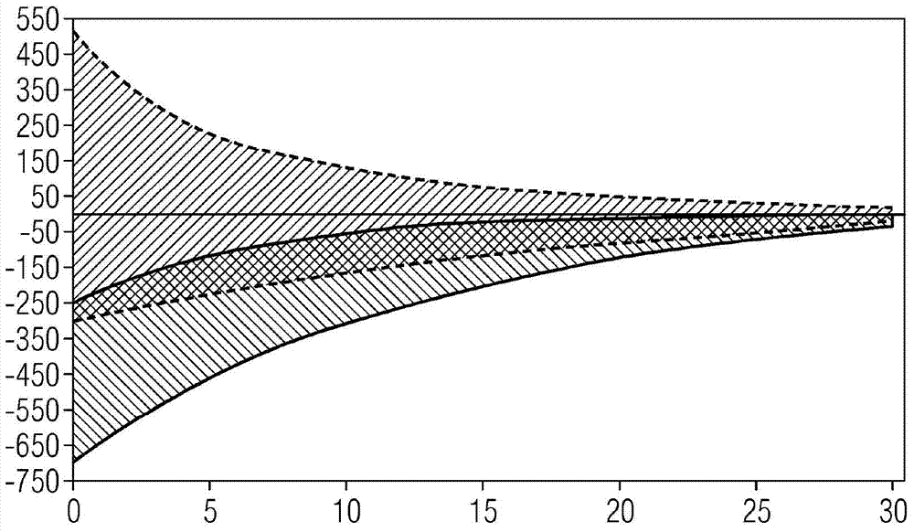
[0026] exist figure 1 The range of internal stress change before and after brushing is shown in . Plot the depth in microns to the right. Plot the internal stress in MPa upwards. The horizontal line in the middle indicates zero internal stress. That is to say, there is neither internal tensile stress nor internal compressive stress there. In the region above this line there is an internal tensile stress. There are internal compressive stresses in the region below this line.

[0027] The hatched area on the right, ie the area between the two dotted lines, indicates in which range the internal stresses of the material milled at a high cutting speed before the brushing lie. It can be recognized here that in many cases undesired internal tensile stresses are present. Of course, there are also cases where internal compressive stress is generated. The hatched area on the left, ie the area between the two solid lines, indicates the value of the internal stress after brushing. ...


PUM

PropertyMeasurementUnit
diameteraaaaaaaaaa
lengthaaaaaaaaaa

Abstract

Machining material, preferably steel, comprises (a) milling the material with such a high cutting speed that residual tensile stresses which exceed a specified value, occur near the surface, and (b) lowering the residual tensile stresses below the specified value by brushing. An independent claim is also included for a brushing device for carrying out the above method.

Description

technical field [0001] The invention relates to a method for processing material by milling and subsequent brushing. Background technique [0002] As a background to the invention, it will be stated in detail that in steam turbines the connection between the turbine shaft and the rotor blades is jointly among the most stressed components. It is therefore also important to keep the internal stress state in the vicinity of the surface after machining in as non-critical a range as possible. If an excessively high internal tensile stress occurs in the region near the surface during processing, this internal tensile stress can cause cracks to develop by superposition with the operating stress. In order to achieve as low as possible or only low internal tensile stresses during machining, well-defined machining or milling parameters, such as cutting and feed rates, depth of cut, etc., are predetermined. Such presets generally result in reduced cutting and feed speeds which often ...

Claims


Application Information

Patent Timeline
Patent Type & Authority Applications(China)
IPC IPC(8): B23P9/00B24B39/00C21D7/04B24B29/00
CPCC21D7/08B24B39/00B24B29/005B24B19/02C21D7/04B23P9/00Y10T29/47Y10T409/303808B23C3/00B23C2220/28B23C2220/44B23C2222/32B23P9/02
Inventor 瓦尔特·大卫沃尔弗拉姆·克诺赫
Owner SIEMENS AG
Why Eureka
Try Eureka