Amplitude phase error correction system and method for transmitting channel of phased-array antenna
A phased array antenna and transmission channel technology, applied in transmitter monitoring and other directions, can solve problems such as error correction, achieve good correction accuracy, and achieve simple engineering effects
- Summary
- Abstract
- Description
- Claims
- Application Information
AI Technical Summary
Problems solved by technology
Method used
Image
Examples
Embodiment Construction
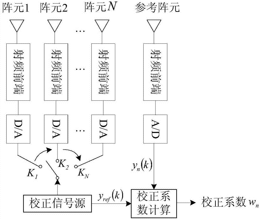
[0028] A uniform circular array phased array antenna consisting of N array elements and their corresponding channels, N transmitting array elements are evenly arranged on a circle, and the center array element is an auxiliary receiving channel array element, such as figure 1 shown. The block diagram of the phased array antenna transmission structure is as follows: figure 2 As shown, the transmitter generates the transmission signal and radiates to free space from the array elements after passing through the D / A and RF front-end. Because the signal transmitted by the phased array antenna is a narrowband signal, within the entire signal bandwidth, the amplitude gain and phase error between channels can be approximated to not change with frequency. Therefore, it is not necessary to consider the signals of different frequencies separately when correcting, and they are all approximately considered to occur at the center frequency, so as long as an amplitude error factor A is intr...
PUM
 Abstract
Description
Claims
Application Information
 - R&D
- Intellectual Property
- Life Sciences
- Materials
- Tech Scout
- Unparalleled Data Quality
- Higher Quality Content
- 60% Fewer Hallucinations
Browse by: Latest US Patents, China's latest patents, Technical Efficacy Thesaurus, Application Domain, Technology Topic, Popular Technical Reports.
© 2025 PatSnap. All rights reserved.Legal|Privacy policy|Modern Slavery Act Transparency Statement|Sitemap|About US| Contact US: help@patsnap.com


