Soft switching control method of buck converter based on optocoupler detection
An optocoupler detection and control method technology, applied in control/regulation systems, output power conversion devices, DC power input conversion to DC power output, etc. Effect
- Summary
- Abstract
- Description
- Claims
- Application Information
AI Technical Summary
Problems solved by technology
Method used
Image
Examples
specific Embodiment approach 1
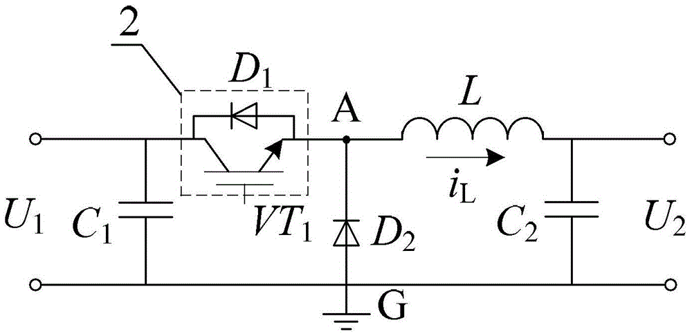
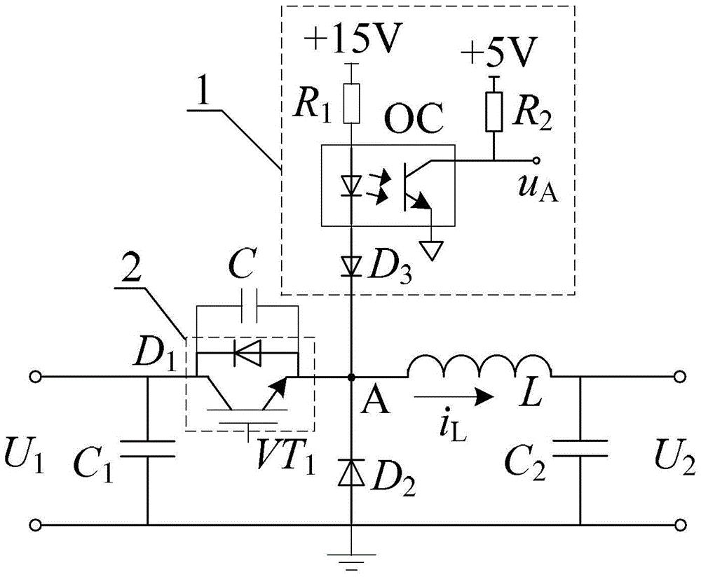
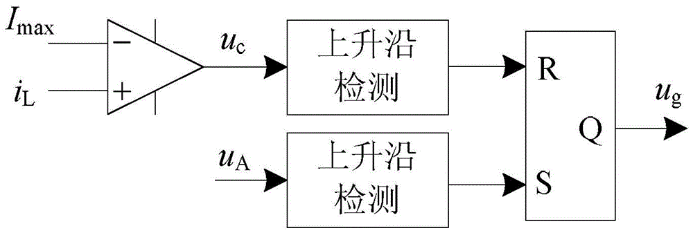
[0023] Specific implementation mode one: the following combination Figure 1 to Figure 3 Describe this embodiment, the Buck converter soft switching control method based on optocoupler detection described in this embodiment, the control method uses the optocoupler detection circuit 1 to detect and obtain the voltage of the midpoint of the Buck converter bridge arm, through the midpoint of the bridge arm The on-off state of the freewheeling diode in the Buck converter is obtained by the voltage, and then the zero-current turn-on signal of the IGBT module 2 is obtained, and then the soft switching control of the Buck converter is realized according to the zero-current turn-on signal; the IGBT module 2 comes with Diode D 1 , and a high-frequency capacitor C is connected in parallel at both ends of the IGBT module 2 .
[0024] In this embodiment, the high-frequency capacitor C is a small-capacity high-frequency capacitor.
specific Embodiment approach 2
[0025] Specific implementation mode two: the following combination figure 1 with figure 2 This embodiment will be described. This embodiment will further describe the first embodiment. The structure of the Buck converter is as follows: a filter capacitor C is connected in parallel between the two input terminals of the Buck converter. 1 , IGBT module 2 and freewheeling diode D 2 The anti-series constitutes the chopping bridge arm, the chopping bridge arm and the filter capacitor C 1 In parallel, the midpoint A of the bridge arm is the IGBT module 2 and the freewheeling diode D 2 The connection point between the bridge arm midpoint A is connected to one end of the filter inductor L, and the other end of the filter inductor L is connected to the output filter capacitor C 2 , filter capacitor C 2 The two ends of are used as the two output ends of the Buck converter;
[0026] The detection end of the optocoupler detection circuit 1 is connected to the midpoint A of the bridg...
specific Embodiment approach 3
[0028] Specific implementation mode three: the following combination figure 2 Describe this embodiment mode. This embodiment mode will further explain Embodiment 2. The optocoupler detection circuit 1 is composed of a high-speed optocoupler OC and its peripheral circuit. The peripheral circuit includes a +15V power supply, a current limiting resistor R 1 , high voltage fast recovery diode D 3 , output pull-up resistor R 2 and +5V power supply, where the +15V power supply shares the ground with the Buck converter, and the +5V power supply is isolated from the Buck converter;
[0029] Between the input terminal and the detection terminal of the optocoupler detection circuit 1, the current limiting resistor R 1 , high-speed photocoupler OC and high-voltage fast recovery diode D 3 In series, the high-voltage fast recovery diode D 3 The cathode of the bridge arm is connected to midpoint A; the optocoupler output signal of optocoupler detection circuit 1 is u A , the optocoupl...
PUM
 Abstract
Description
Claims
Application Information
 - R&D Engineer
- R&D Manager
- IP Professional
- Industry Leading Data Capabilities
- Powerful AI technology
- Patent DNA Extraction
Browse by: Latest US Patents, China's latest patents, Technical Efficacy Thesaurus, Application Domain, Technology Topic, Popular Technical Reports.
© 2024 PatSnap. All rights reserved.Legal|Privacy policy|Modern Slavery Act Transparency Statement|Sitemap|About US| Contact US: help@patsnap.com


