An integrated engine brake rocker arm structure
An integrated braking mechanism technology, applied in the direction of engine components, machines/engines, mechanical equipment, etc., can solve the problems of high manufacturing and assembly costs, asymmetric load of the valve bridge, and failure to work normally, so as to shorten the stroke of the oil circuit , Easy installation and adjustment, improved sensitivity and reliability
- Summary
- Abstract
- Description
- Claims
- Application Information
AI Technical Summary
Problems solved by technology
Method used
Image
Examples
Embodiment 1
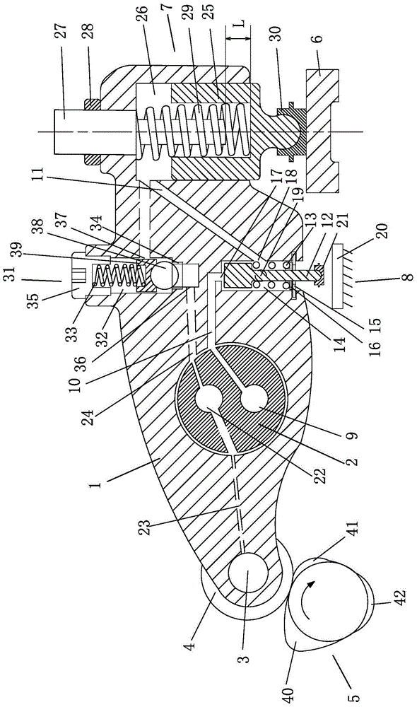
[0039] Embodiment 1: see figure 1 :
[0040]An integrated engine brake rocker structure, the rocker arm 1 is set on the rocker shaft 2, one end of the rocker arm 1 is provided with a roller 4 through a pin 3, the pin 3 is a copper pin, and the roller 4 is in contact with the exhaust cam 5 Connected, the other end of the rocker arm 1 is provided with a brake mechanism 7 for operating the exhaust valve bridge 6, and the exhaust valve bridge 6 is provided under the brake mechanism 7, and the brake mechanism 7 controls the action of the exhaust valve bridge 6. An oil control valve mechanism 8 is installed on the rocker arm 1 between the brake mechanism 7 and the rocker arm shaft 2, a brake oil passage 9 and a lubricating oil passage 22 are arranged on the rocker arm shaft 2, and a communication oil control valve mechanism is provided on the rocker arm 1. The first brake oil passage 10 of the valve mechanism 8, and the second brake oil passage 11 connecting the oil control valve m...
Embodiment 2
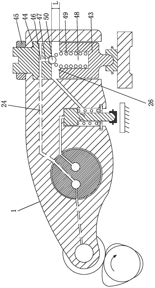
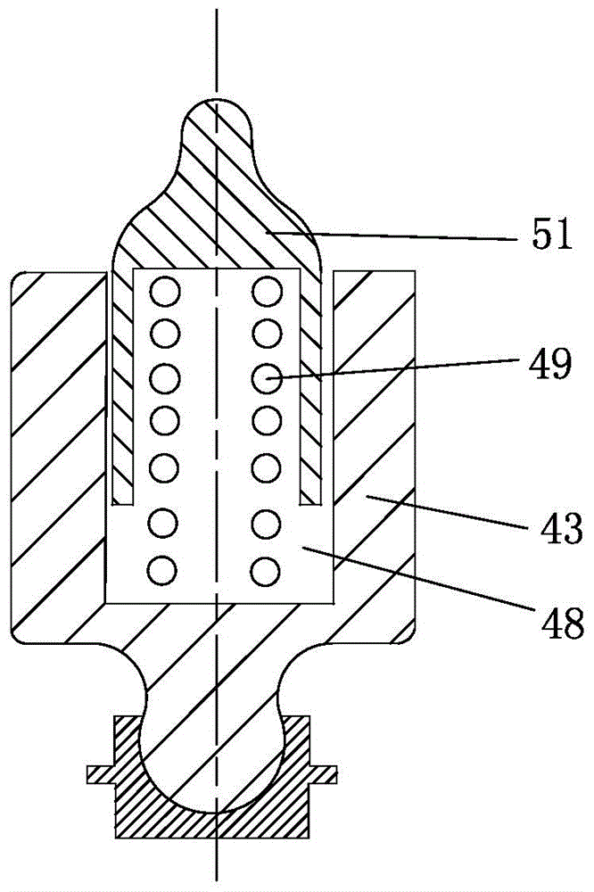
[0056] Example 2: see figure 2 , 3 :
[0057] The structure of this embodiment is basically the same as that of Embodiment 1, the difference being that the braking mechanism 7 of this embodiment has a self-contained check valve structure.
[0058] The brake mechanism 7 is as follows: the brake piston 43 is arranged in the brake chamber 26 on the rocker arm 1 close to the exhaust valve end, the upper end of the brake chamber 26 is provided with an adjustment bolt 44, and the adjustment bolt 44 passes through the lock nut 45 fixed, the adjusting bolt 44 is provided with a radial oil hole 46 and an axial oil hole 47, the radial oil hole 46 communicates with the second lubricating oil passage 24, and the axial oil hole 47 communicates with the blind hole 48 on the brake piston 43, A spring 49 is arranged in the blind hole 48, and the upper end of the spring 49 is provided with a steel ball 50 or a valve core 51 with a ball head. The compensation gap L between the upper end of ...
Embodiment 3
[0060] Embodiment 3: See Figure: 4-6:
[0061] The structure of this embodiment is basically the same as that of Embodiment 1, the difference being that the structure of the oil control valve mechanism is different:
[0062]The oil control valve mechanism 8 is: the oil control valve plunger 52 is installed in the lower piston chamber of the rocker arm 1, and the oil control valve plunger 52 is respectively provided with annular grooves 53, 54 and an axially arranged straight groove 55 for connecting the two annular grooves 53, 54; one end of the spring piece 56 is fixed on one side of the rocker arm 1 by a bolt 57, and the other end is clamped on the lower part of the oil control valve plunger 52 On the annular groove 54, two guide bolts 58, 59 are screwed on the rocker arm 1, and the inner ends of the two guide bolts 58, 59 are arranged in the straight groove 55 of the oil control valve plunger 52. Under normal conditions, the oil control valve plunger 52 is in the upper non...
PUM
 Abstract
Description
Claims
Application Information
 - Generate Ideas
- Intellectual Property
- Life Sciences
- Materials
- Tech Scout
- Unparalleled Data Quality
- Higher Quality Content
- 60% Fewer Hallucinations
Browse by: Latest US Patents, China's latest patents, Technical Efficacy Thesaurus, Application Domain, Technology Topic, Popular Technical Reports.
© 2025 PatSnap. All rights reserved.Legal|Privacy policy|Modern Slavery Act Transparency Statement|Sitemap|About US| Contact US: help@patsnap.com


