
Discharge hopper for belt conveyor

A technology of belt conveyor and discharge hopper, which is applied in the direction of conveyor objects, transportation and packaging, etc., to achieve the effect of slowing down the kinetic energy of materials, slowing down the load-bearing condition, and reliably buffering and absorbing impact

Active Publication Date: 2016-09-28
TONGLING MIRACLE MECHANICAL EQUIP
View PDF11 Cites 0 Cited by
  • Summary
  • Abstract
  • Description
  • Claims
  • Application Information

AI Technical Summary

Problems solved by technology

[0003] The object of the present invention is to provide a reasonable and practical belt conveyor unloading funnel, which can flexibly solve the problem of material kinetic energy release in traditional unloading funnels during unloading, and can effectively ensure that the funnel and the bottom are The normal and reliable operation of the tape machine

Method used


Image

  • Discharge hopper for belt conveyor
  • Discharge hopper for belt conveyor
  • Discharge hopper for belt conveyor

Examples


Embodiment Construction

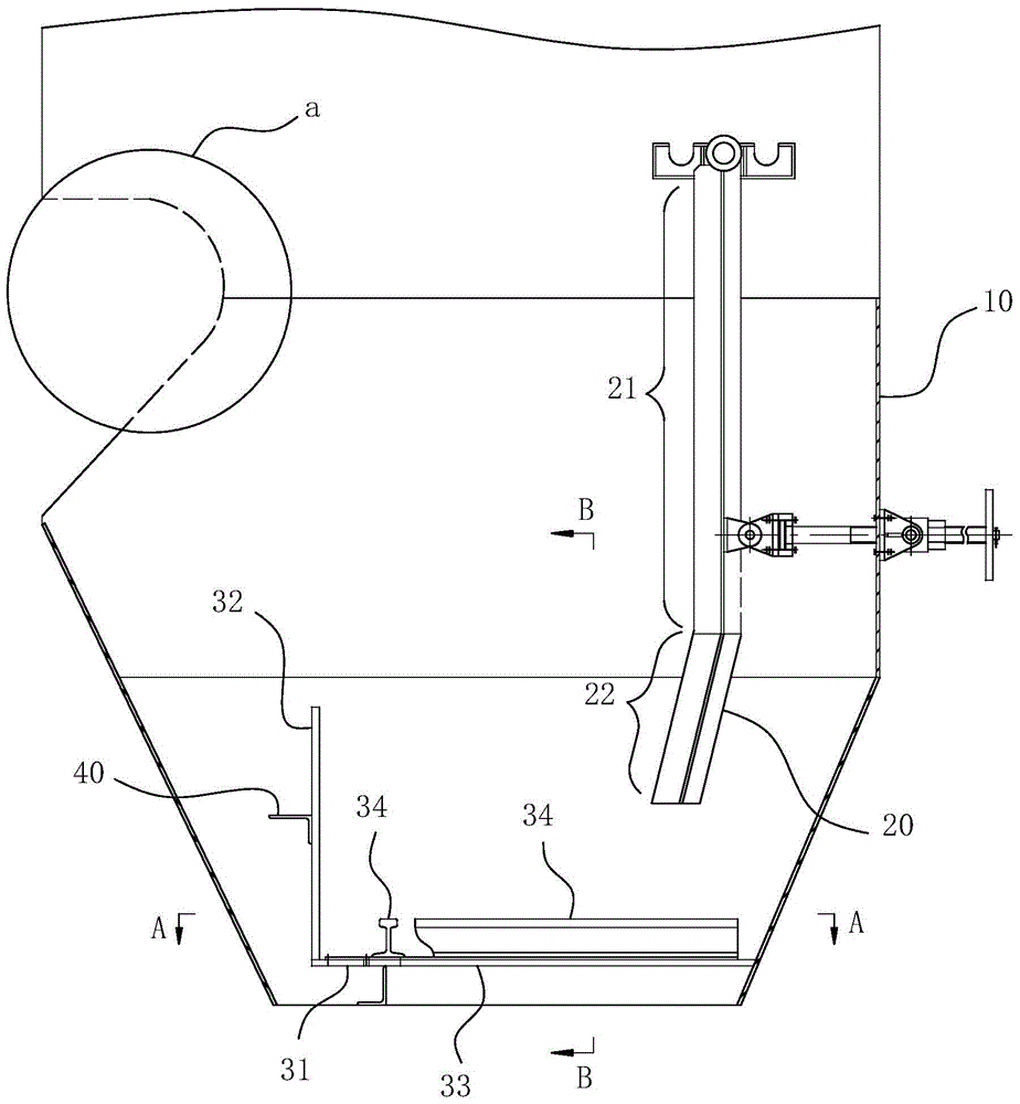
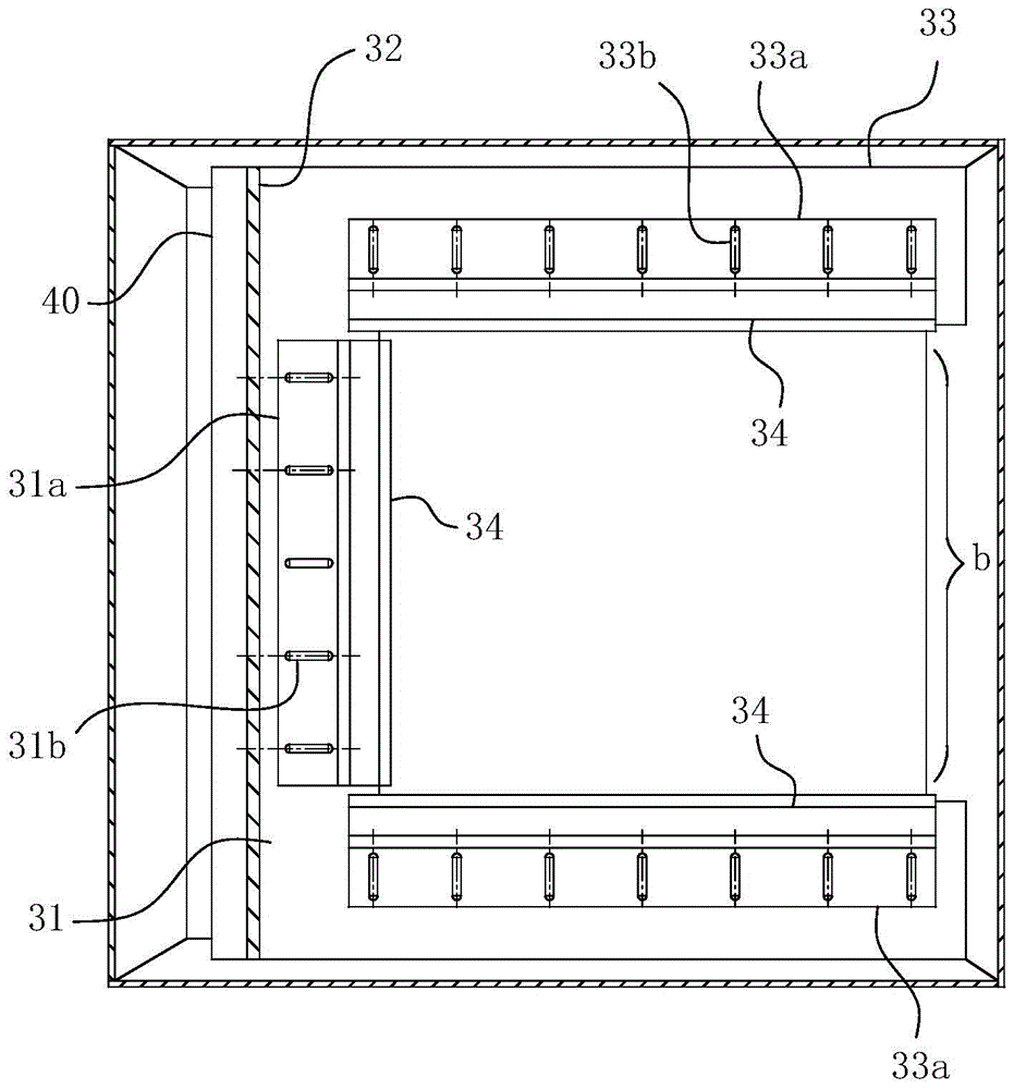
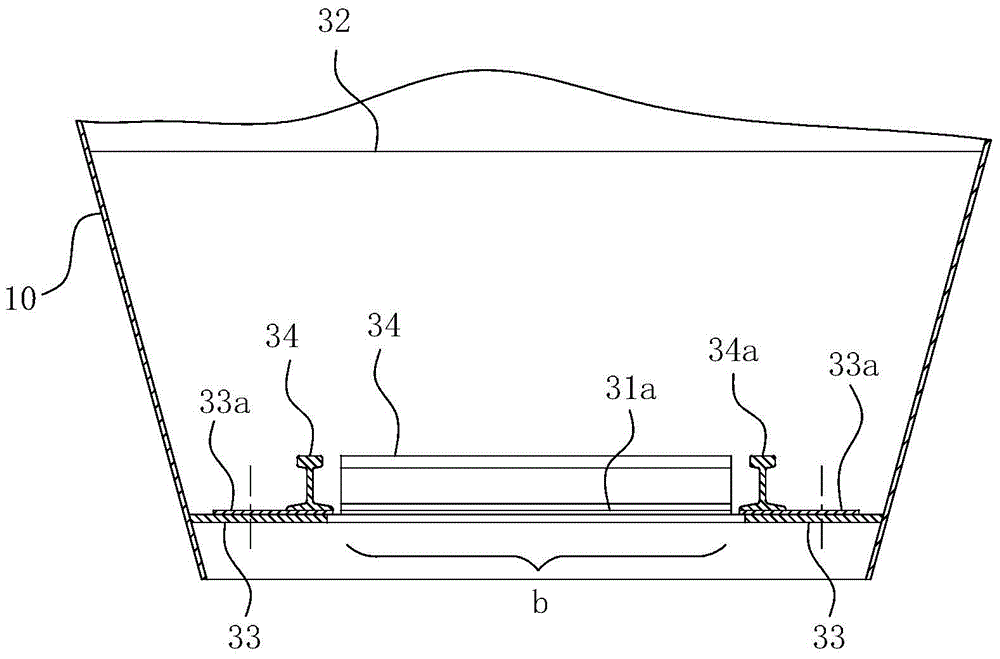
[0029] combine here Figure 1-3 The specific implementation structure and work flow of the present invention are described as follows:

[0030] The specific structure of the present invention is as Figure 1-3 As shown, a funnel 10 and a diversion baffle 20 disposed in the funnel 10 are included. Two installation grooves are welded and fixed at two opposite inner side walls of the funnel 10 . The diversion baffle 20 is in the shape of a long groove, and the bottom of the groove is fixedly connected with a hinged shaft. layout. The mounting groove is provided with a plurality of notches which form snap fit with the hinge shaft, and the notches are all opened upwards. After the deflector baffle 20 is engaged and suspended at the installation groove by the hinge shaft at its top, the hanging position of the deflector baffle 20 can be adjusted by replacing the engaged installation groove to adjust the falling point of the material.

[0031] For ease of understanding, here, the ...


PUM


Abstract

The invention relates to the field of discharge equipment for conveyer belts, in particular to a discharge hopper for belt conveyers. The discharge hopper comprises a hopper body and a guide damper fixed or hinged to the inside of the hopper body; storage cell units are further disposed within the hopper body; an opening of each storage cell unit is located at a material fall path of the guide damper and points to a material fall direction of the guide damper; the storage cell units are at least distributed on two sidewalls of the hopper body, close to a discharge opening of the hopper body, and the rear wall of the hopper body; the inner edge of each storage cell unit and the front wall of the hopper body form a discharge opening of the hopper body, and each discharge opening discharges material into a receiving system below; the bottom of each storage cell unit is provided with an adjusting plate whereby the width of the storage cell unit can be adjusted; the inner edge of each storage cell unit is fixed on the corresponding adjusting plate. The discharge hopper has the advantage that reliable running of the hopper and the belt conveyer below can be effectively ensured.

Description

technical field [0001] The invention relates to the field of conveyor belt unloading equipment, in particular to a discharge funnel for a belt conveyor. Background technique [0002] Belt conveyor, as a standing conveying system, has always been indispensable as an important part of the material conveying system. The discharge funnel device is one of the important parts of the belt conveyor, and its main functions include guiding material, controlling the direction of material flow and preventing dust. In order to control the direction of material flow, a diversion baffle is usually arranged inside the front wall of the funnel. The specific installation is as follows: the two side walls of the head shield above the funnel are provided with several installation grooves for hanging the deflector baffle. A hinge shaft is arranged at the top of the deflector baffle. The deflector baffle is clamped and suspended on the installation groove through the hinge shaft, and when nece...

Claims


Application Information

Patent Timeline
Patent Type & Authority Patents(China)
IPC IPC(8): B65G47/44
Inventor 翟宏维
Owner TONGLING MIRACLE MECHANICAL EQUIP
Learn More