Combined lifeboat
A lifeboat and combined technology, which is applied to lifesaving in water, ships, and ship safety, etc., can solve the problems of transporting difficult lifeboats to their destinations, and achieve the effects of improving mobility, reducing self-weight, and facilitating disassembly and assembly.
- Summary
- Abstract
- Description
- Claims
- Application Information
AI Technical Summary
Problems solved by technology
Method used
Image
Examples
no. 1 example
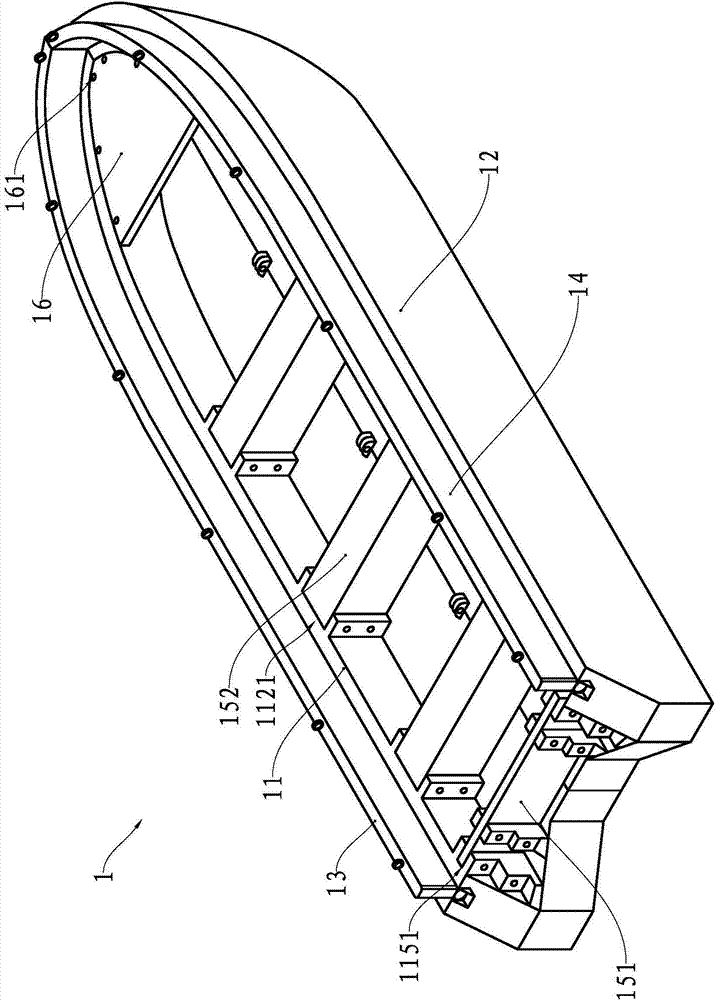
[0026] The combined lifeboat consists of a left half body, a right half body, a port side wall panel, a starboard side wall panel, a beam and a transverse plate.
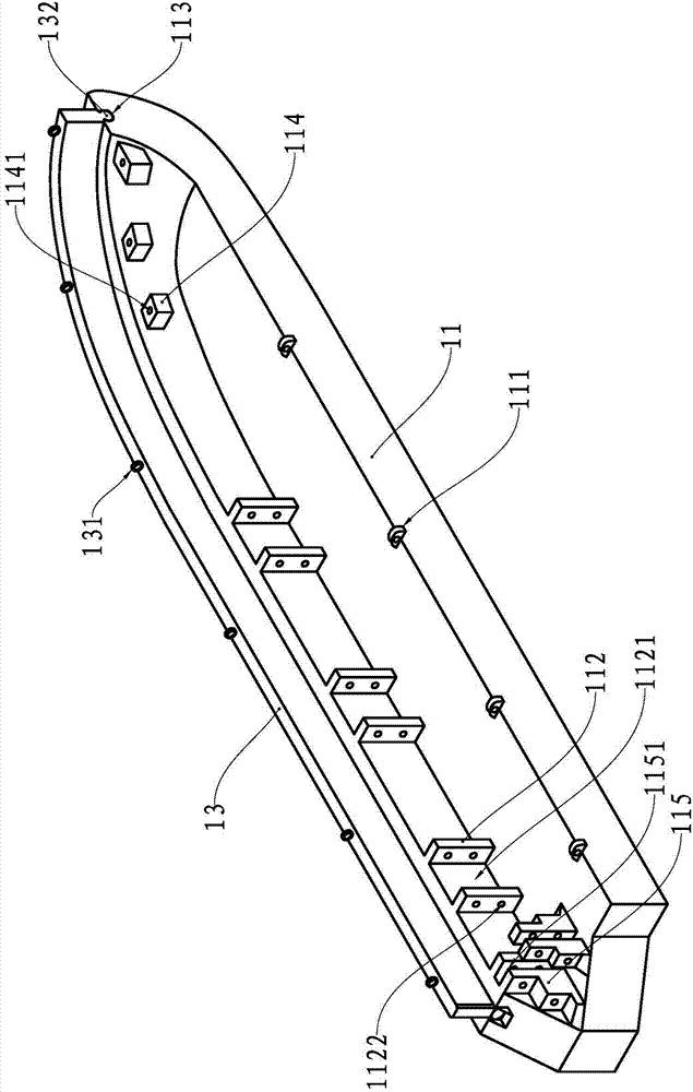
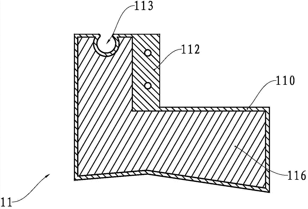
[0027] see figure 1 , the top surface of the port side plate of the left half body 11 is formed with a tongue and groove 113 arranged along the top surface line, the bottom surface of the port side wall plate 13 is formed with a tenon 132 matching the tenon and groove 113, the upper surface of the port side wall 13 A plurality of rope buckles 131 are fixed for tying up the rope so that people in the water can grasp the rope. Three bosses 112, three bosses 114 and one boss 115 are formed on the inner side wall of the port side plate. The boss 112 is formed with a card slot 1121 extending vertically, and the boss 115 is formed with a A vertically extending locking slot 1151 , and a vertically extending screw hole 1141 is formed on the boss 114 . The bottom plate protrudes upwards to form four earrings 111 .
[0028...
no. 2 example
[0035] As an explanation of the second embodiment of the present invention, only the differences from the above-mentioned first embodiment will be described below.
[0036] see Figure 5 , the stern plate 251 of the combined lifeboat 2 is a hanger plate for installing the propeller 27, the bow is not installed with a transverse plate, the transverse beam also includes a vertical plate type beam 253, and the vertical plate type beam 253 is detachable through the transverse bolt and the card slot 21121 The ground is fixedly connected; the riser beam 253 and the bow of the left half body 21 and the right half body 22 enclose a storage compartment 28. The width of the riser type beam 253 along the boat length direction is preferably 0.5 cm to 10 cm.
[0037] see Image 6 , the left half body 21 and the right half body 22 are detachably fixedly connected at the bottom plate through the upper and lower rows of earrings 221 and the cooperation of the earrings 211 and bolts.
[003...
no. 3 example
[0040] As a description of the third embodiment of the present invention, only the differences from the above-mentioned second embodiment will be described below.
[0041]see Figure 8 , the left half body 31 and the right half body 32 are detachably fixedly connected at the bottom plate through the cooperation of the lower earrings 311 and the bolts.
PUM
 Abstract
Description
Claims
Application Information
 - R&D Engineer
- R&D Manager
- IP Professional
- Industry Leading Data Capabilities
- Powerful AI technology
- Patent DNA Extraction
Browse by: Latest US Patents, China's latest patents, Technical Efficacy Thesaurus, Application Domain, Technology Topic, Popular Technical Reports.
© 2024 PatSnap. All rights reserved.Legal|Privacy policy|Modern Slavery Act Transparency Statement|Sitemap|About US| Contact US: help@patsnap.com


