CNC (computer numerical control) rotary clamp of machining center

A technology of rotating clamping device and machining center, which is applied in the direction of positioning device, metal processing equipment, metal processing machinery parts, etc., can solve the problems of large quality of the main fixture, high labor intensity, low work efficiency, etc., to improve processing performance and The effect of machining accuracy, flexible adjustment and simple structure

Active Publication Date: 2015-04-08
深圳博尚精密制造有限公司
View PDF5 Cites 5 Cited by
  • Summary
  • Abstract
  • Description
  • Claims
  • Application Information

AI Technical Summary

Problems solved by technology

[0004] The device for clamping the workpiece on the existing machining center mainly has the following disadvantages: 1. Poor versatility. For different products, it is often necessary to replace different main fixtures, resulting in high labor intensity and low work efficiency
2. The main fixture is heavy and heavy, and the load capacity of its driving mechanism is high, so it is difficult to measure and guarantee the accuracy

Method used


Image

  • CNC (computer numerical control) rotary clamp of machining center

Examples


Embodiment Construction

[0013] The present invention will be further described below in conjunction with specific drawings and embodiments.

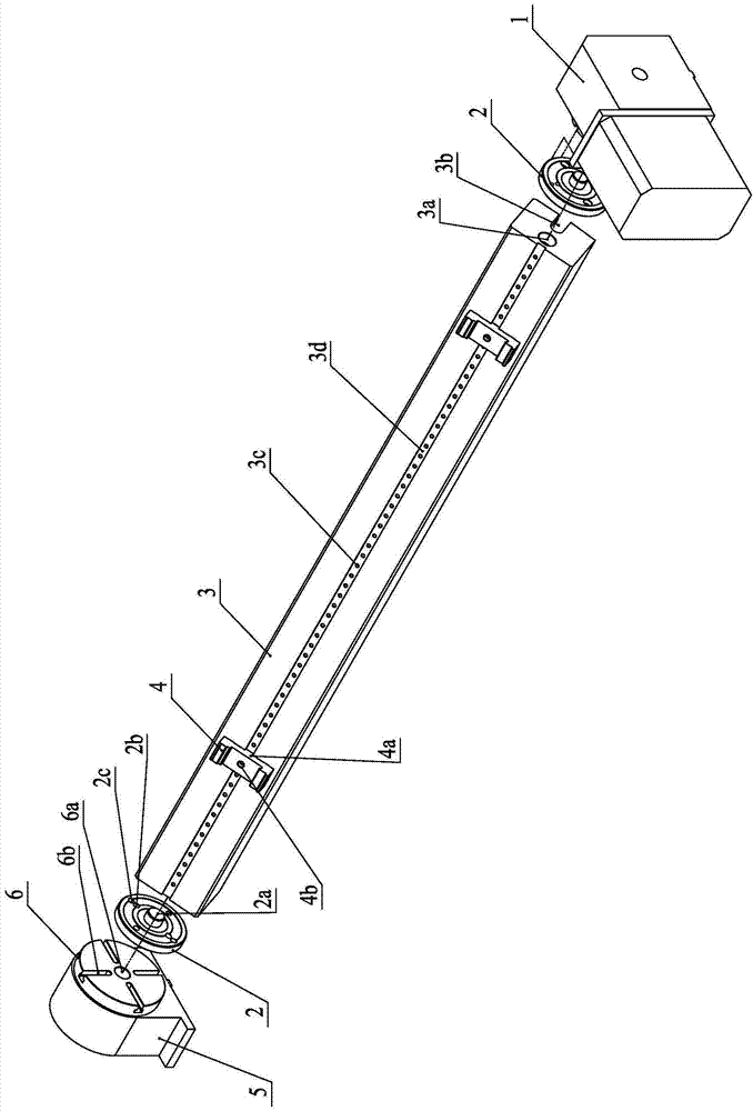
[0014] As shown in the figure: the CNC rotary clamping device of the machining center in the embodiment is mainly composed of a main clamp 3 , a CNC indexing head 1 , a tailstock 5 and a workpiece clamp 4 .

[0015] like figure 1 As shown, the main fixture 3 is elongated, the head end of the main fixture 3 is connected to the numerical control indexing head 1, and the tail end of the main fixture 3 is rotatably supported and installed on the tailstock 5; the front surface of the main fixture 3 is set There are several first installation holes 3c uniformly distributed along the length direction of the main fixture 3, the workpiece holder 4 is provided with a second installation hole 4a, and the workpiece holder 4 is installed in the first installation hole 3c and the second installation hole 4a The screws are fastened on the front surface of the main fixture 3...


PUM


Abstract

The invention relates to a CNC (computer numerical control) rotary clamp of a machining center. The CNC rotary clamp comprises a main clamp, a CNC index head, a tailstock and a workpiece clamp. The main clamp is elongated; the CNC index head is connected to the head of the main clamp; the tail of the main clamp is rotatably supported on the tailstock. The front surface of the main clamp is provided with a plurality of first mounting holes evenly distributed along the length of the main clamp. The workpiece clamp is provided with a second mounting hole. The workpiece clamp is fixed to the front surface of the main clamp through screws mounted in the first mounting holes and the second mounting hole. The CNC rotary clamp is simple in structure, firm to mount and flexibly adjustable and helps improve machining performance and precision of a four-axis linkage vertical machining center.

Description

technical field [0001] The invention relates to an accessory part of a machining center, in particular to a numerical control rotary clamping device of a four-axis linkage vertical machining center, which belongs to the technical field of machining equipment. Background technique [0002] Machining center is a typical high-tech mechanical processing equipment, and its development represents a country's design and manufacturing level. The machining center has a strong comprehensive processing ability, and can complete more processing steps after the workpiece is clamped and positioned once. The machining center is suitable for single-piece processing with complex shapes and high precision requirements, and small and medium-sized batches of multi-variety processing. It is also an important symbol to judge the technical ability and craft level of the enterprise. Today, machining centers have become the mainstream direction of modern machine tool development and are widely used...

Claims


Application Information

Patent Timeline
Patent Type & Authority Applications(China)
IPC IPC(8): B23Q3/06
CPCB23Q3/04
Inventor 吕国栋包为能
Owner 深圳博尚精密制造有限公司
Why Eureka
Try Eureka