Buoyancy switch and automatic paddy field irrigation mechanism comprising buoyancy switch

A technology of buoyancy switch and automatic irrigation, which is applied to engine components, mechanical equipment, watering devices, etc., can solve the problems of troublesome, time-consuming, and inconvenient operation.

Inactive Publication Date: 2015-04-08
杨立军
View PDF14 Cites 2 Cited by
  • Summary
  • Abstract
  • Description
  • Claims
  • Application Information

AI Technical Summary

Problems solved by technology

When the lowest-level field reaches the irrigation stop water level, close the water injection port. During this period, personnel are required to guard to prevent the waste of water resources. However, large-scale irrigation takes a long time and is inconvenient to operate. In addition, it is affected by evaporation and crop absorption. Influenced by frequent irrigation, each irrigation requires a long time of guarding, and the operation is very troublesome
[0004] Although there are some automatic irrigation mechanisms that use water level sensors to cooperate with water pumps and other equipment, the overall mechanism is cumbersome, the investment and operation costs are relatively high, and long-term management and maintenance are required, so it is not suitable for large-scale paddy fields and small farmers.

Method used


Image

  • Buoyancy switch and automatic paddy field irrigation mechanism comprising buoyancy switch
  • Buoyancy switch and automatic paddy field irrigation mechanism comprising buoyancy switch

Examples


Embodiment Construction

[0036] The specific implementation manners of the present invention will be further described in detail below in conjunction with the accompanying drawings and embodiments. The following examples are used to illustrate the present invention, but are not intended to limit the scope of the present invention.

[0037] In the description of the present invention, unless otherwise specified, the orientation or state relationship indicated by the terms "upper", "lower", "top", "bottom", "longitudinal" etc. is based on the orientation or state relationship shown in the drawings , is only for the convenience of describing the present invention and simplifying the description, but does not indicate or imply that the referred device or element must have a specific orientation, be constructed and operated in a specific orientation, and thus should not be construed as limiting the present invention.

[0038] In the description of the present invention, it should be noted that unless other...


PUM


Abstract

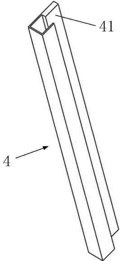
The invention relates to the technical field of paddy field irrigation, and provides a buoyancy switch and an automatic paddy field irrigation device comprising the buoyancy switch. The buoyancy switch is arranged on a paddy field piece to be irrigated; the automatic paddy field irrigation system further comprises a water trough, a flashboard, elastic pieces and a pull rope, wherein the water trough is arranged between the paddy field piece to be irrigated and a water trench for irrigation and is used for leading water in the water trench for irrigation into the paddy field piece to be irrigated; two guide slots with opposite notches are correspondingly formed in two sides of the water inlet side of the water trough; a cross beam is connected between the tops of the two guide slots; two sides of the lower part of the flashboard are respectively inserted into the two guide slots in a sliding manner; the elastic pieces are connected between the upper part of the flashboard and the water trough in a tensioning manner; one end of the pull rope is connected with the lower part of the flashboard, and the other end of the pull rope bypasses through the upper side of the cross beam and is connected with a second rotating hook. When a water level in the paddy field piece to be irrigated reaches a preset water level, the buoyancy switch is turned on, and the flashboard is closed under the action of the tension of the elastic pieces so as to close the water inlet side of the water trough; therefore the aim of automatic irrigation is fulfilled. A system is simple in structure and convenient to operate.

Description

technical field [0001] The invention relates to the technical field of paddy field irrigation, and in particular provides a buoyancy switch and a paddy field automatic irrigation mechanism including the buoyancy switch. Background technique [0002] Paddy fields are arable land for planting aquatic crops. The growth of aquatic crops requires a certain suitable water level. The existing paddy field irrigation usually builds a canal next to the ridge on one side of the paddy field, and introduces the water in the canal by opening a water injection port on the ridge. to the paddy fields. [0003] When irrigating, it is necessary to artificially open and close the water injection port. Once the irrigation reaches the stop irrigation water level, the water injection port needs to be closed immediately. Paddy fields usually exist in the form of terraced fields, and the irrigation of terraced fields usually adopts the method of series irrigation. First, the water in the canal need...

Claims


Application Information

Patent Timeline
Patent Type & Authority Applications(China)
IPC IPC(8): A01G25/16
CPCF16K31/30A01G25/16
Inventor 杨立军
Owner 杨立军
Why Eureka
Try Eureka