Zero-pressure drip irrigation system

A dripper and head cover technology, which is applied in the direction of climate change adaptation, horticulture, botany equipment and methods, etc., can solve the problems of high cost of drip irrigation system, high operating cost, easy blockage of drippers, etc., to reduce equipment purchase costs and The effect of running costs

Active Publication Date: 2015-04-08
甘肃亚盛亚美特节水有限公司
View PDF6 Cites 6 Cited by
  • Summary
  • Abstract
  • Description
  • Claims
  • Application Information

AI Technical Summary

Problems solved by technology

[0003] However, the disadvantages of the current drip irrigation technology are: drip irrigation uses water with a certain pressure, and the drip irrigation system must be equipped with water pumps, filters, control and measurement equipment (pressure gauges, control valves, flow regulators, etc.), water transmission and distribution pipelines at all levels And drippers, therefore, the drip irrigation system is expensive, once called "expensive technology", only used in high value-added economic crops; because impurities will make the drippers easy to block, so the water source should be strictly filtered, high operating costs

Method used


Image

  • Zero-pressure drip irrigation system
  • Zero-pressure drip irrigation system

Examples


Embodiment Construction

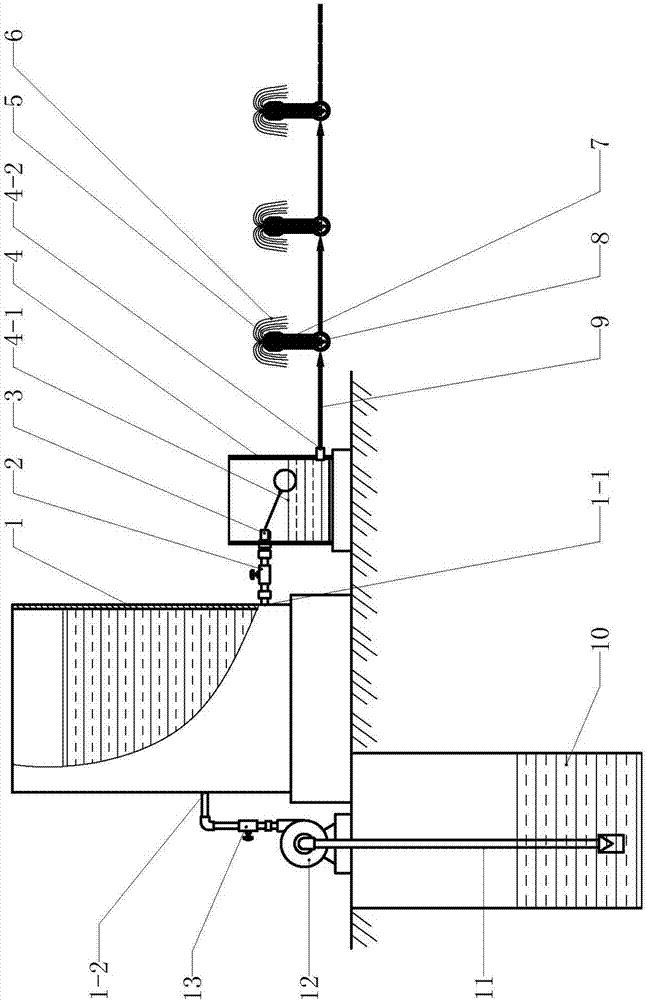
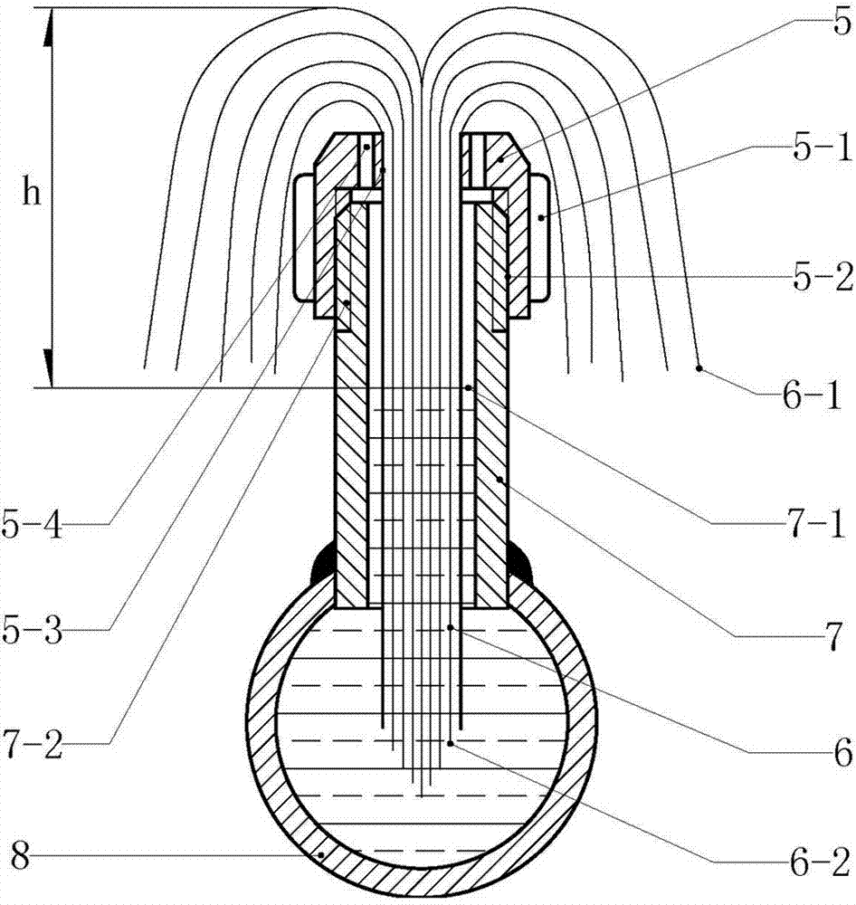
[0014] Example figure 1 and figure 2 In the embodiment shown, a pressureless drip irrigation system is composed of a water storage tank (1), a balance water tank (4), a water supply pipe (9), a water diversion branch pipe (8), a water diversion capillary (7) and a capillary dripper, wherein , the water supply pipe (9) and the water diversion branch pipe (8) each have a branch interface; the upper end of the water diversion capillary (7) has a connecting thread (7-2); the capillary dripper consists of a dripper cover (5) and a capillary bundle (6 ), the dripper cover (5) is a revolving structure, there is an air vent (5-4) on the top of the dripper cover (5), and there is a bayonet (5-3) in the center of the revolving body of the dripper cover (5). ), the capillary bundle (6) is installed in the bayonet (5-3) of the dripper cover (5), there is a mounting screw (5-2) inside the wall of the dripper cover (5), and the dripper cover (5) (5) There is a hand-twisting ear flap (5...


PUM


Abstract

The invention relates to a drip irrigation device, in particular to a zero-pressure drip irrigation system which is composed of a water storage tank, a balance water tank, a water supply pipe, water diversion branched pipes, water diversion capillaries and capillary drippers. Each capillary dripper is composed of a dripper cover and a capillary bundle which is mounted in a bayonet of the dripper cover, each dripper cover is mounted at the upper end of the corresponding water diversion capillary, the lower end of each water diversion capillary is connected onto a branch port of the corresponding water diversion branched pipe, the lower end of each capillary bundle extends into the corresponding water diversion branched pipe through in-pipe space of the corresponding water diversion capillary while the upper end of the same is led out of the bayonet of the corresponding dripper cover, an inlet end of each water diversion branched pipe is connected onto a branch port of the water supply pipe, an inlet end of the water supply pipe is connected onto a supplied water output port of the balance water tank, a floating ball valve is connected into the balance water tank, and an inlet end of the floating ball valve is connected onto a water outgoing port of the water storage tank. A capillary principle is utilized to achieve the objective of drip irrigation, the water supply pipe does not need pressure, and the drippers cannot be blocked, so that equipment purchasing expense and running expense are lowered, and drip irrigation technology is enabled to be inexpensive.

Description

technical field [0001] The invention relates to drip irrigation technology, in particular to a drip irrigation device. Background technique [0002] Drip irrigation technology is an irrigation method that drips water and nutrients required by crops into the soil in the root zone of crops evenly and slowly through a low-pressure pipeline system and an irrigator installed on a capillary tube according to the water requirements of crops. The main feature of drip irrigation is that the amount of irrigation water is small, the duration of one irrigation is longer, and the cycle of irrigation is short. Waste, the water utilization rate can reach 95%. Compared with sprinkler irrigation, drip irrigation has a higher effect of saving water and increasing production. At the same time, it can be combined with fertilization to more than double the fertilizer efficiency. It is suitable for irrigation of fruit trees, vegetables, commercial crops and greenhouses, and can also be used for ...

Claims


Application Information

Patent Timeline
Patent Type & Authority Applications(China)
IPC IPC(8): A01G25/02
CPCA01G25/02A01G25/023Y02A40/22
Inventor 吴水仙
Owner 甘肃亚盛亚美特节水有限公司
Why Eureka
Try Eureka