Automatic measurement equipment for profile and position of logo mounting hole

A technology for automatic measurement and installation of holes, applied to measuring devices, optical devices, instruments, etc., can solve the problems that the optical three-coordinate measuring instrument is not suitable, is not suitable for ordinary production workshops, and cannot meet the needs of rapid production. Suitable for batch use, reducing cost pressure, and low equipment cost

Inactive Publication Date: 2015-04-01
HANS LASER TECH IND GRP CO LTD
View PDF6 Cites 24 Cited by
  • Summary
  • Abstract
  • Description
  • Claims
  • Application Information

AI Technical Summary

Problems solved by technology

For example, as a general-purpose measuring device, an optical three-coordinate measuring instrument can realize the above-mentioned measurement with custom-made fixtures and light sources, but its cost is high; in addition, it has high requirements for the use environment: air cleanliness, noise, temperature, etc. It is not suitable for use in ordinary production workshop environments; moreover, it is generally equipped with only one measuring head, which can only scan and measure step by step, with low efficiency and cannot meet the needs of rapid production
It can be seen that the optical three-coordinate measuring instrument is not well suited for the application of batch manufacturing of products

Method used


Image

  • Automatic measurement equipment for profile and position of logo mounting hole
  • Automatic measurement equipment for profile and position of logo mounting hole
  • Automatic measurement equipment for profile and position of logo mounting hole

Examples


Embodiment Construction

[0024] Now in conjunction with the accompanying drawings, the preferred embodiments of the present invention will be described in detail.

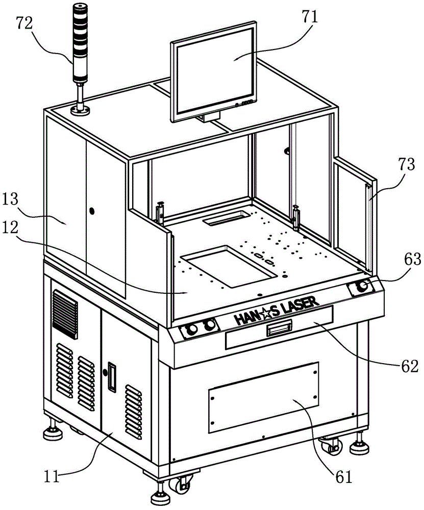
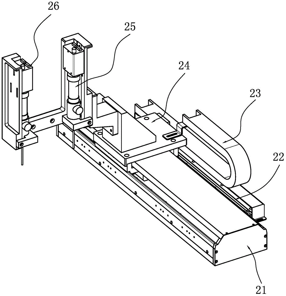
[0025] The present invention proposes an automatic measurement device for the profile and position of the installation hole of the mark, which uses multiple sets of precision servo motion platforms equipped with grating rulers to drive multiple industrial cameras equipped with customized light sources to take pictures, and conduct data analysis through customized software , so as to achieve high-precision and high-efficiency non-contact measurement.

[0026] The present invention adopts the industrial computer as the core control unit of the equipment, and controls the execution unit through compatible motion control cards, I / O cards, image acquisition cards, etc., such as platform movement, light source on and off, camera photography, etc.; The precision servo motion platform, through the real-time feedback signal of the grating ruler, es...


PUM


Abstract

The invention relates to the field of measurement equipment, in particular to automatic measurement equipment for the profile and the position of a logo mounting hole. The automatic measurement equipment comprises a processing device as well as three precision servo motion platforms and five cameras which are controlled by the processing device, wherein a first precision servo motion platform drives a first camera and a second camera to perform shooting scanning on two long edges of a rectangular casing of a to-be-measured product, a second precision servo motion platform drives a third camera and a fourth camera to perform shooting scanning on two short edges of the rectangular casing of the to-be-measured product, a third precision servo motion platform drives a fifth camera and a second camera to perform shooting scanning on the logo mounting hole of the to-be-measured product, and the processing device can calculate the profile and the position of the logo mounting hole according to the measurement data provided by the five cameras. The automatic measurement equipment can be well applied to the application condition of batch product manufacture.

Description

technical field [0001] The invention relates to the field of measuring equipment, in particular to a non-contact optical automatic measuring equipment. Background technique [0002] At this stage, the functional homogeneity of electronic products is relatively serious, which prompts consumers to pay more attention to the attractiveness of product appearance. Based on this, the design, processing and assembly of LOGO (logo), which is an important part of the product appearance, must be refined to meet the increasingly high aesthetic requirements of consumers. [0003] An existing electronic product made of metal has a rectangular housing, on which a LOGO mounting hole is arranged, and the LOGO mounting hole is divided into upper and lower parts, located in the middle of the rectangular housing. Since the shape of the installation hole of the LOGO is a complex curve shape, in order to ensure the qualified processing quality, it is necessary to measure the contour and position...

Claims


Application Information

Patent Timeline
Patent Type & Authority Applications(China)
IPC IPC(8): G01B11/24G01B11/00
Inventor 高泽润刘建华吴顺柏王刚范小卫艾晓国刘朋飞陈振余仝敬烁尹建刚高云峰
Owner HANS LASER TECH IND GRP CO LTD
Why Eureka
Try Eureka