
Medium-and-low speed magnetic levitation railway low route continuous framework type bearing rail beam structure and construction method

A technology of low-lying lines and frame beams, which is applied to the continuous frame-type rail-beam structure of low-speed magnetic levitation low-lying lines and its construction field, which can solve the problems of difficulty in making integral formwork and many construction procedures, and achieve convenient and simplified construction control The construction process and the effect of reducing the difficulty of positioning

Active Publication Date: 2015-04-01
CHINA RAILWAY SIYUAN SURVEY & DESIGN GRP
View PDF8 Cites 15 Cited by
  • Summary
  • Abstract
  • Description
  • Claims
  • Application Information

AI Technical Summary

Problems solved by technology

[0007] 2. In order to increase the rigidity and deformation resistance of the pier, the upper part of the pier is often equipped with longitudinal and transverse beams. In order to save the amount of work, the cross-sectional size of these longitudinal and transverse beams is usually smaller than that of the pier. In the middle, it is difficult to make the overall formwork, and the buttresses and the longitudinal and transverse tie beams are integrally poured. It is necessary to construct the buttresses first, and then construct the longitudinal and transverse tie beams. There are many construction procedures.

Method used


Image

  • Medium-and-low speed magnetic levitation railway low route continuous framework type bearing rail beam structure and construction method
  • Medium-and-low speed magnetic levitation railway low route continuous framework type bearing rail beam structure and construction method
  • Medium-and-low speed magnetic levitation railway low route continuous framework type bearing rail beam structure and construction method

Examples


Embodiment Construction

[0032] Below in conjunction with accompanying drawing and specific embodiment the present invention is described in further detail:

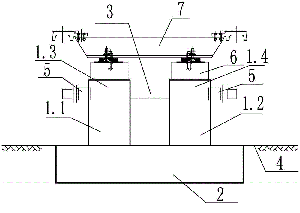
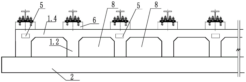
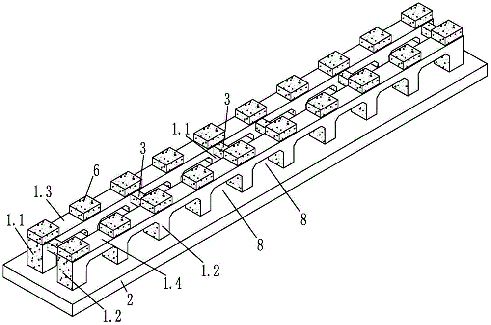
[0033] like Figure 1~3 The continuous frame-type rail-bearing beam structure of the medium and low-speed magnetic levitation low-set line shown includes a reinforced concrete bottom plate 2, a rail row 7, and multiple rows of sleeper pedestals 6 arranged along the line direction, and it also includes a left top plate 1.3 of the reinforced concrete continuous frame beam. , the right top plate 1.4 of the reinforced concrete continuous frame beam, a plurality of reinforced concrete continuous frame beams arranged at equal intervals along the direction of the line on the reinforced concrete bottom plate 2, the left frame column 1.1, and a plurality of left frame columns 1.1 arranged at equal intervals along the direction of the line on the reinforced concrete bottom plate 2 The right frame column 1.2 of the reinforced concrete continuous frame beam...


PUM


Abstract

The invention discloses a medium-and-low speed magnetic levitation railway low route continuous framework type bearing rail beam structure. The structure comprises a reinforced concrete bottom plate, a rail row, a plurality of rows of sleeper pedestals, reinforced concrete continuous frame beam top plates and a plurality of reinforced concrete continuous frame beam frame posts, wherein flow guide rail supporting bases are arranged on the outer side of the left reinforced concrete continuous frame beam top plate and the outer side of the right reinforced concrete continuous frame beam top plate; a plurality of reinforced concrete cross beams which are arranged along the route direction are connected between the inner side of the left reinforced concrete continuous frame beam top plate and the inner side of the right reinforced concrete continuous frame beam top plate; a longitudinal arch is formed between every two adjacent left reinforced concrete continuous frame beam frame posts; a longitudinal arch is also formed between every two adjacent right reinforced concrete continuous frame beam frame posts. The structure is high in stability and strength, and convenient to construct and maintain, a cable can penetrate through a bearing rail beam, and a cable pipeline is not required to be pre-buried in a bearing rail beam lower geotechnical foundation.

Description

technical field [0001] The invention relates to the technical field of low-level line structures for medium-low speed maglev traffic, in particular to a continuous frame-type rail-supporting beam structure for low-level medium-speed maglev lines and a construction method thereof. Background technique [0002] Medium and low-speed maglev rail transit is a new type of transportation. At present, there are few research results at home and abroad, and there are even fewer lines in operation around the world. At present, there are only the commercial operation line of the medium and low speed maglev railway in Japan in March 2005-Eastern Hills Line and the commercial operation line of the medium and low speed maglev railway in South Korea in June 2014. China's medium and low-speed maglev transportation currently only has the National University of Defense Technology test line, the Qingchengshan test line, and the Tangshan test line, and there is no line officially put into operat...

Claims


Application Information

Patent Timeline
IPC IPC(8): E01B25/30E01D19/00E01D21/00
CPCE01B25/305E01B29/005E01B2204/09
Inventor 郭建湖李小和王勇刚谢瑞丰黄国良杨辉建
Owner CHINA RAILWAY SIYUAN SURVEY & DESIGN GRP
Learn More