
Emitter coupled asymmetrical logic protection triggering system

A technology of emitter coupling and logic protection, which is applied in the direction of pulse generation, electrical components, and electric pulse generation, can solve the problems of unfavorable circuit system performance stability, susceptibility to external electromagnetic interference, and sudden change of current, so as to overcome external electromagnetic interference, Easy to make and use, and prevent the effect of sudden changes in current

Inactive Publication Date: 2015-03-25
CHENGDU CHUANGTU TECH
View PDF0 Cites 1 Cited by
  • Summary
  • Abstract
  • Description
  • Claims
  • Application Information

AI Technical Summary

Problems solved by technology

However, the trigger circuits currently used by people are not only complex in structure, but also susceptible to external electromagnetic interference, especially when the connected load changes due to temperature, these traditional trigger circuits will show nonlinear working conditions. It will produce a large current mutation, which is not conducive to the performance stability of the connected circuit system

Method used


Image

  • Emitter coupled asymmetrical logic protection triggering system
  • Emitter coupled asymmetrical logic protection triggering system

Examples


Embodiment Construction

[0015] The present invention will be described in further detail below in conjunction with the embodiments and the accompanying drawings, but the embodiments of the present invention are not limited thereto.

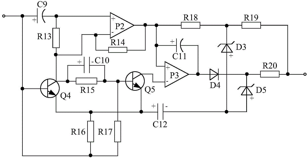
[0016] like figure 1 As shown, the present invention is mainly composed of an emitter-coupled asymmetric circuit, a passive π-type filter circuit, a beam-excited logic amplifier circuit and a logic-protected emitter-coupled amplifier circuit.

[0017] Wherein, the beam-excited logic amplifying circuit is mainly composed of power amplifier P1, NAND gate IC1, NAND gate IC2, and NAND gate IC3. Polar capacitor C6, one end is connected to the positive pole of polar capacitor C6, the other end is grounded resistor R9 after diode D2, the positive pole is connected to the connection point of resistor R9 and diode D2, and the negative pole is grounded Polar capacitor C8, one end is connected to The resistor R10 connected to the negative input terminal of the NAND gate IC1 and th...


PUM


Abstract

The invention discloses an emitter coupled asymmetrical logic protection triggering system. The system is mainly composed of an emitter coupled asymmetrical circuit, a passive pi type filtering circuit, and a light beam excitation logic amplifying circuit connected between the emitter coupled asymmetrical circuit and the passive pi type filtering circuit in series. The system is characterized in that the light beam excitation logic amplifying circuit is mainly composed of a power amplifier P1, a NAND gate IC1, a NAND gate IC2, a NAND gate IC3, a polar capacitor C6, a resistor R9 and a polar capacitor C8 and the like, the negative electrode of the polar capacitor C6 is connected with the positive electrode input end of the power amplifier P1, the positive electrode of the polar capacitor C6 is grounded through a light emitting diode D1, one end of the resistor R9 is connected with the positive electrode of the polar capacitor C6, the other end of the resistor R9 is grounded through a diode D2, and the positive electrode of the polar capacitor C8 is connected with the point where the resistor R9 is connected with the diode D2. The system is simple in overall structure and quite convenient to manufacture and use. Meanwhile, the system is stable in performance, capable of effectively overcoming external electromagnetic interference and capable of effectively preventing current break.

Description

technical field [0001] The invention relates to a trigger circuit, in particular to an emitter coupling asymmetric logic protection trigger system. Background technique [0002] The trigger circuit is a circuit widely used by people at present, and it is widely used in fields such as electronics and electrical equipment. However, the trigger circuits currently used by people are not only complex in structure, but also susceptible to external electromagnetic interference, especially when the connected load changes due to temperature, these traditional trigger circuits will show nonlinear working conditions. A large sudden change in current will be generated, which is not conducive to the stable performance of the connected circuit system. Contents of the invention [0003] The purpose of the present invention is to overcome the defect that the current trigger circuit is prone to sudden change of current when the external load changes, which is not conducive to the stabilit...

Claims


Application Information

Patent Timeline
IPC IPC(8): H03K3/011
Inventor 谢静周鹏程
Owner CHENGDU CHUANGTU TECH
Learn More