An easy-to-install cable tray

A cable tray, easy installation technology, applied to electrical components and other directions, can solve problems such as cumbersome construction steps, and achieve the effects of high production cost, simple structure and low construction cost

Inactive Publication Date: 2017-01-18
YIYANG ELECTRICITY MANAGEMENT +1
View PDF9 Cites 0 Cited by
  • Summary
  • Abstract
  • Description
  • Claims
  • Application Information

AI Technical Summary

Problems solved by technology

[0004] It is known that the cable tray is mainly used for laying cables on the building, and the cable can be closed on the building through the cable tray. format and other structures; cable trays use brackets, brackets and installation accessories where conditions permit, and use cable trays to avoid accidents from being exposed to cables and being directly contacted by other objects; cable trays can be installed in bridges and culverts. To reduce secondary damage to buildings without cable trenches, "cutting grooves on buildings to hide cables" also has aesthetic effects; but the existing cable bridge structures suitable for installation at the bottom of bridges and at the top of culverts are channel steel, By fixing the channel-shaped cable tray on the bottom of the bridge or the top of the culvert, the steel plates on both sides of the connection wall are welded at intervals at the lower opening. When in use, the cables are inserted into the channel-shaped cable tray on the upper part of the steel plate, and then use the plug-in bottom plate Close the lower opening. The use of this structure must disconnect the cable close to the bridge or culvert, and then connect the disconnected part of the cable after the construction is completed. In the operation of loading the old cable into the cable bridge, it is necessary to cut off the power. Therefore, the construction steps are cumbersome

Method used


Image

  • An easy-to-install cable tray
  • An easy-to-install cable tray

Examples


Embodiment Construction

[0018] The present invention can be explained in more detail with reference to the following examples; however, it should be noted that the present invention is not limited to the following examples; the purpose of disclosing the present invention is to protect all changes and improvements within the scope of the present invention.

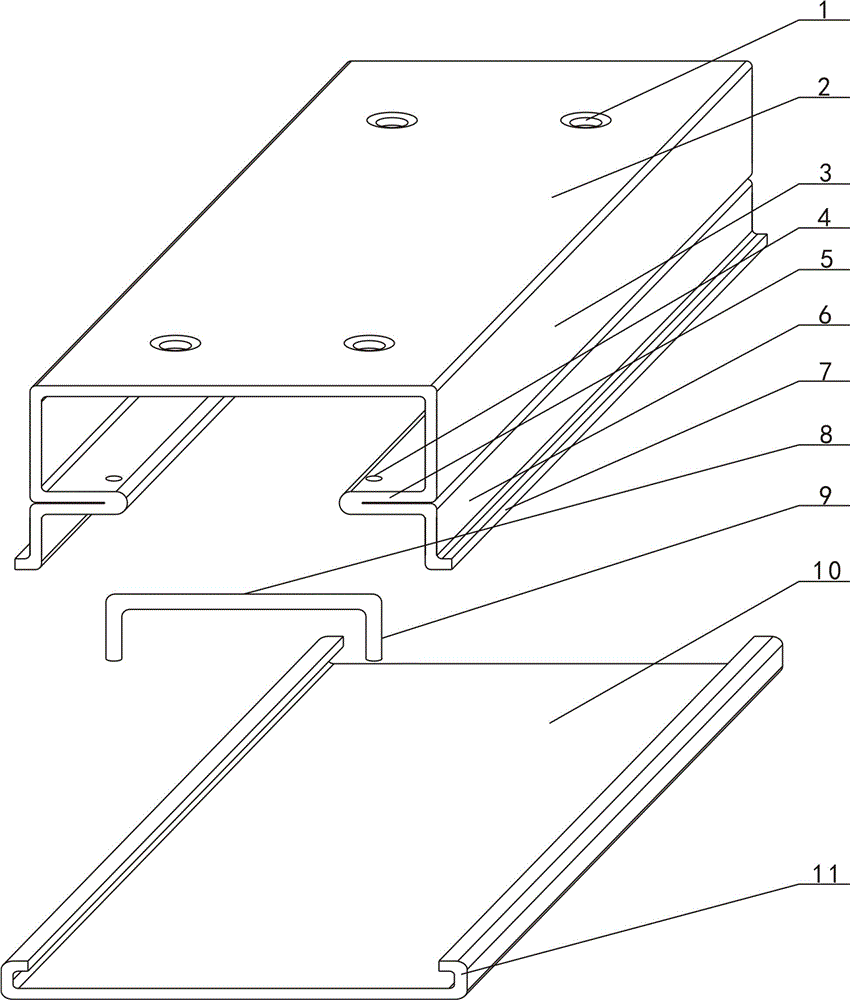
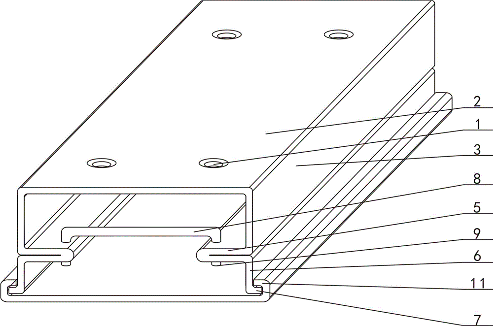
[0019] combined with figure 1 Or the convenient installation cable tray described in 2, comprising a top plate 2, a vertical plate, an inner folding plate 5, a support rod 8, and a bottom buckle plate 10, and a plurality of installation holes 1 are arranged at intervals on the top plate 2, and the top plate 2 There are two rows of mounting holes 1 arranged on the top plate, and the two rows of mounting holes 1 are respectively arranged on the two sides of the top plate 2 and are arranged at intervals. The lower parts of the two sides of the top plate 2 are respectively provided with vertical plates, and the two vertical plates are respectively prov...


PUM


Abstract

The invention relates to a cable bridge convenient to install and relates to a cable bridge. A top plate (2) is provided with a plurality of installation holes (1) at intervals, vertical plates are arranged on the lower portions of the two sides of the top plate respectively, inward-folding plates (5) are arranged on the parts, close to the lower portions, of the two vertical plates respectively, corresponding insertion holes (4) are formed in the two inward-folding plates at intervals, vertical rods (9) are arranged on the lower portions at the two ends of each supporting rod (8) and inserted in the corresponding two insertion holes, a cable containing space is formed between the upper portions of the supporting rods and the top plate, and inward flangings (11) are arranged on the two sides of a bottom buckling plate (10) and are clamped to outward flangings (7) arranged at the lower ends of the two vertical plates. According to the cable bridge convenient to install, the supporting rods which are movably connected in an insertion mode are used for replacing existing welded and integrated steel plates, a cable does not need to be cut off in the construction process, and the purpose of electrified construction is achieved.

Description

[0001] 【Technical field】 [0002] The invention relates to a cable bridge, in particular to a conveniently installed cable bridge. [0003] 【Background technique】 [0004] It is known that the cable tray is mainly used for laying cables on the building, and the cable can be closed on the building through the cable tray. format and other structures; cable trays use brackets, brackets and installation accessories where conditions permit, and use cable trays to avoid accidents from being exposed to cables and being directly contacted by other objects; cable trays can be installed in bridges and culverts. To reduce secondary damage to buildings without cable trenches, "cutting grooves on buildings to hide cables" also has aesthetic effects; but the existing cable bridge structures suitable for installation at the bottom of bridges and at the top of culverts are channel steel, By fixing the channel-shaped cable tray on the bottom of the bridge or the top of the culvert, the steel p...

Claims


Application Information

Patent Timeline
Patent Type & Authority Patents(China)
IPC IPC(8): H02G3/04
Inventor 冯希明赵红霞范佳瑛孙玮皓
Owner YIYANG ELECTRICITY MANAGEMENT
Why Eureka
Try Eureka