
Laser sintering device and sintering method

A laser sintering and equipment technology, which is applied in the direction of electrical components, circuits, and energy efficiency improvement, can solve problems such as damage and glass glue cracks, and achieve the effects of reducing temperature difference, reducing stress, avoiding cracks and even damage

Active Publication Date: 2015-03-25
BOE TECH GRP CO LTD +1
View PDF4 Cites 12 Cited by
  • Summary
  • Abstract
  • Description
  • Claims
  • Application Information

AI Technical Summary

Problems solved by technology

[0004] The purpose of the technical solution of the present invention is to provide a laser sintering equipment and a sintering method, which is used to solve the problem that the glass glue forms cracks or breaks due to the large shrinkage stress generated by laser sintering when laser packaging is used in the prior art display manufacturing process

Method used


Image

  • Laser sintering device and sintering method
  • Laser sintering device and sintering method
  • Laser sintering device and sintering method

Examples


Embodiment Construction

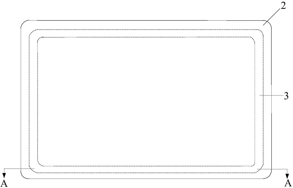
[0044] In order to make the object, technical solution and advantages of the present invention clearer, the present invention will be described in detail below with reference to the accompanying drawings and specific embodiments.

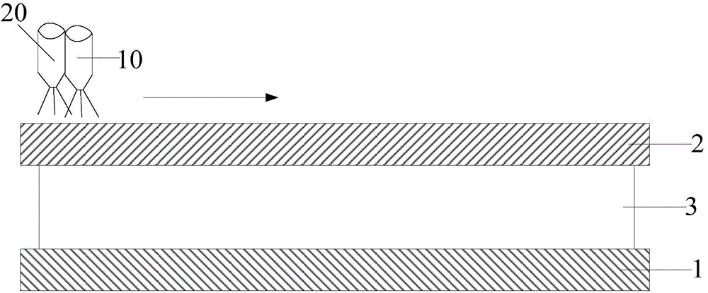
[0045] The laser sintering equipment described in the specific embodiment of the present invention, the laser sintering equipment includes:

[0046] The first laser head is used to output the laser with the first power;

[0047] The second laser head is used to output the laser with the second power;

[0048] The driving device is used to drive the first laser head and the second laser head to move, so that the first laser head and the second laser head respectively heat the same area on the material to be sintered.

[0049] The laser sintering equipment described in the embodiment of the present invention adds a laser head on the basis of the laser head used in the existing laser packaging, and uses two laser heads to heat the material to be sinte...


PUM


Abstract

The invention provides a laser sintering device and sintering method. The laser sintering device comprises a first laser head used for outputting a laser of first power, a second laser head used for outputting a laser of second power and a drive device used for driving the first drive head and the second drive head to move, and the first laser head and the second laser head are made to heat the same area of a material to be sintered. When the two laser heads are used for heating the to-be-sintered material arranged on a to-be-sintered device, the two laser heads are made to heat a certain to-be-heated area of the to-be-sintered material, therefore, the to-be-sintered material is preheated before laser sintering, or annealing treatment is carried out on the to-be-sintered material after laser sintering, therefore, the difference of the temperature obtained before laser sintering and the temperature in the laser sintering process is reduced, or the reducing speed of the temperature obtained after laser sintering is reduced, so that the stress of a substrate of the to-be-sintered material is reduced, and the situation that cracks or even damage is caused by shrinkage stress is avoided.

Description

technical field [0001] The invention relates to the technical field of display manufacturing, in particular to a laser sintering equipment and a sintering method. Background technique [0002] An organic light-emitting diode (Organic Light-Emitting Diode, OLED) display device is a display device that drives a light-emitting material to emit light autonomously by an electric current. Since the light-emitting materials in OLED displays are very sensitive to temperature, air, and water, good packaging is crucial to the lifespan and picture quality of OLED displays. There are many packaging technologies for OLED displays, such as laser encapsulation, thin film encapsulation, and injection encapsulation. Among them, laser packaging technology is a relatively mature OLED packaging technology at present. Its main working principle is to use the precise and rapid heating and melting of laser to sandwich two glass substrates (one is cover glass, and the other is provided with lumine...

Claims


Application Information

Patent Timeline
Patent Type & Authority Applications(China)
IPC IPC(8): H01L51/56
CPCB22F12/45B22F12/226H10K59/8722H10K71/421Y02P10/25B29C2035/0838C03C27/06H10K71/00H10K50/8426B29C35/0805
Inventor 肖昂
Owner BOE TECH GRP CO LTD
Learn More