Cable manufacturing equipment

A technology for manufacturing equipment and cables, which is applied in the field of cable manufacturing equipment to achieve the effects of increasing the length of storage lines, increasing the speed of pay-off, and improving the efficiency of cable manufacturing

Inactive Publication Date: 2015-03-25
HENAN COMM CABLE
View PDF4 Cites 1 Cited by
  • Summary
  • Abstract
  • Description
  • Claims
  • Application Information

AI Technical Summary

Problems solved by technology

[0003] The purpose of the present invention is to provide a cable manufacturing equipment to solve the problem in the prior art that the cable will have a deflection force when it winds through the wire storage

Method used


Image

  • Cable manufacturing equipment
  • Cable manufacturing equipment

Examples


Embodiment Construction

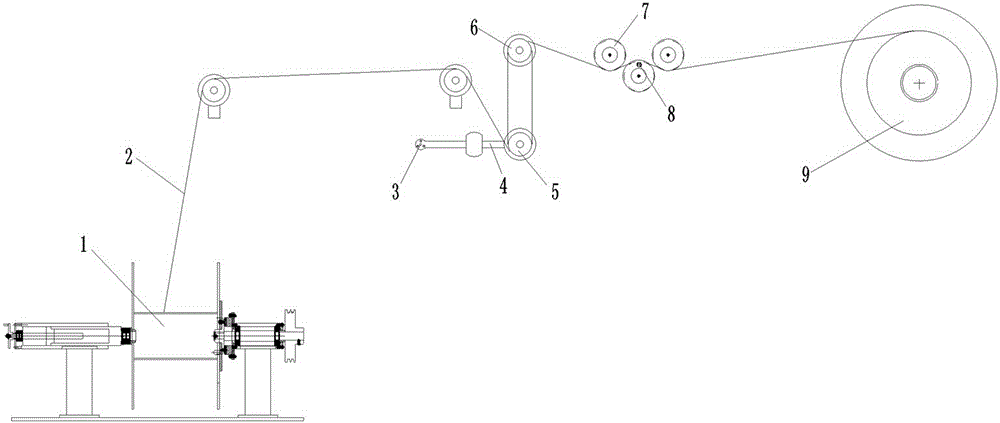
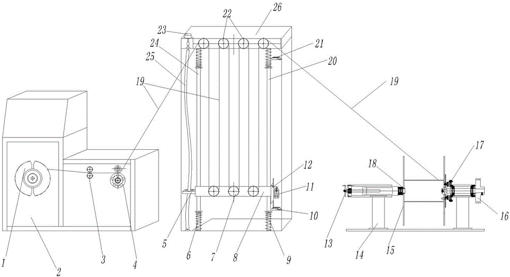
[0013] Examples of cable manufacturing equipment are figure 2 Shown: it includes a wire storage device, a pay-off reel and a take-up reel, the pay-off reel is provided with a brake pad 17, the pay-off reel is connected to the pay-off drive mechanism through the pay-off drive pulley 16, and the pay-off reel is arranged on the pay-off On the reel frame 14, the pay-off reel frame is provided with a pay-off reel top-tight handle 13 and a pay-off top cone 18; the take-up reel 1 is arranged on the take-up reel frame 2, and the take-up reel frame 2 is provided with a wire arrangement 3 and a pair of pressure rollers 4, the pressure rollers are assembled on the take-up reel frame 2 through a one-way bearing, and one of the pressure rollers is a meter pressure roller provided with a meter meter proximity switch. After the cable is drawn out from the pay-off reel, it is wound around the fixed reel and the movable reel of the cable storage in turn, and finally drawn out through the fixe...


PUM


Abstract

The invention relates to cable manufacturing equipment. The cable manufacturing equipment comprises a cable storage device which comprises a rack, at least two fixed reels with rotation axes extending in the front-back direction are sequentially arranged on the rack in the left-right direction, the rack is provided with a guide structure with the guide direction extending in the up-down direction, a movable tensioning frame is movably assembled on the guide structure in a guide mode, the portion, below the fixed reels, of the movable tensioning frame is provided with one or at least two movable reels sequentially distributed in left-right direction in a rotating mode, the rotation axes of the movable reels extend in the front-back direction, and the movable reels and the fixed reels are provided with reel grooves around which a cable is wound in the same plane. The cable manufacturing equipment solves the problem that deflecting force exists when a cable is wound around a cable storage device in the prior art.

Description

technical field [0001] The present invention relates to cable manufacturing equipment. Background technique [0002] Existing cable manufacturing equipment such as figure 1 Shown: it includes a pay-off reel 1, a wire accumulator, a crimping wheel 7 and a take-up reel 9, the crimping wheel is provided with a meter-counting proximity switch 8, and the wire accumulator includes a plurality of fixed reels 6 and a plurality of moving Reel 5, a reel groove is arranged on the movable and fixed reels, each fixed reel is arranged on a coaxial line, each movable reel is arranged on a coaxial line, and a tension swing rod is arranged on the movable reel 4. A potentiometer 3 is set on the tension pendulum. The cable 2 on the pay-off reel is wound on the take-up reel 9 after passing through the wire accumulator and the crimping wheel. On the moving and fixed winding reels, the function of the wire storage device is to prevent the cable from being fluffy. The existing problem with this...

Claims


Application Information

Patent Timeline
IPC IPC(8): H01B13/00
Inventor 宋广平李琳李雅莉
Owner HENAN COMM CABLE
Why Eureka
Try Eureka