Eureka AIR delivers breakthrough ideas for toughest innovation challenges, trusted by R&D personnel around the world.

Control line pay-off machine

A technology for controlling lines and pay-off machines, which is applied in the direction of conveying filamentous materials, thin material handling, transportation and packaging, etc., can solve the problems of manual pay-off, many employees, and high labor intensity, and achieve the number and length of pay-off lines. Accurate, fast pay-off speed and low labor intensity

Inactive Publication Date: 2013-10-30
CRRC LUOYANG CO LTD
View PDF0 Cites 0 Cited by
  • Summary
  • Abstract
  • Description
  • Claims
  • Application Information

AI Technical Summary

Problems solved by technology

[0003] The traditional laying-out method has the following disadvantages: (1) It requires many employees, about 6, with slow speed and low efficiency, which cannot meet the production needs and often affects the production node; (2) Putting the control line of a locomotive requires a total of It takes 50,000 meters to walk, and the labor intensity is high, which is a test for the health of the employees. After working for a long time, it is easy to get occupational diseases such as varicose veins; (3) Manual setting out, the effect is poor, and human errors will inevitably occur, which will affect the production progress and cause waste.

Method used


Image

  • Control line pay-off machine
  • Control line pay-off machine

Examples


Embodiment Construction

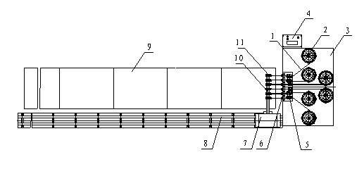
[0011] Such as figure 2 As shown, the pay-off machine of the present invention is mainly composed of 1 workbench 3, at least 6 wire extenders 5 and 6 bolt cutters 6, 1 trolley 7, 1 track 8, 1 storage table 9, and 1 Pay-off rack 10, 6 wire clamps 11, 1 control box 4 form. The control box 4 is installed on the side of the workbench 3, and the control box 4 is equipped with electrical control components including a computer to ensure automatic control of the pay-off machine and automatic pay-off; the rectangular workbench 3 is provided with at least 6 pay-off racks 2. The pay-off frame 2 includes a base and a turntable, and the turntable can be rotated; the side of the workbench 3 is equipped with wire extenders 5 equal in number to the pay-off frame 2, and each wire extender 5 has 2 tensioning wheels for control The line 1 plays a certain tensioning effect; the outer surface of the workbench 3 is equipped with bolt cutters 6 equal to the number of the pay-off frame 2, and the ...


PUM


Abstract

The invention discloses a control line pay-off machine, and relates to a pay-off machine capable of paying off a plurality of control lines at one step. The control line pay-off machine mainly solves problems that an internal combustion locomotive is provided with more than 600 control lines, the control lines are mainly paid off manually traditionally, only one control line can be paid off by one person at a time, the speed and the efficiency are low, the labor intensity is high, and the pay-off lengths are inaccurate. The control line pay-off machine comprises at least six pay-off racks and control lines arranged on turntables of the pay-off racks, and is characterized in that the pay-off racks are arranged on a workbench, line tensioners are arranged on a side surface of the workbench, the quantity of the line tensioners corresponds to that of the pay-off racks, line clippers are arranged on the outer side surface of the workbench, and line clamps are arranged on a trolley which is arranged on tracks. The control line pay-off machine has the advantages that the lines are pulled and paid off by the electric trolley, accordingly, the control line pay-off machine is high in speed and efficiency and low in labor intensity and is controlled by a computer, and the pay-off quantity and the pay-off lengths are quite accurate.

Description

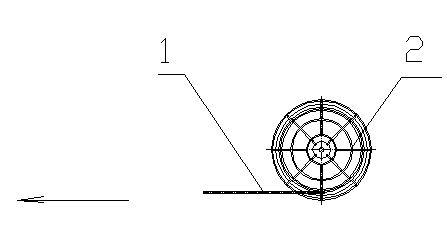
technical field [0001] The invention relates to a wire pay-off machine, in particular to a wire pay-off machine capable of placing multiple wire control wires at one time. Background technique [0002] A known diesel locomotive has more than 600 control lines, and each line has a length of 30 to 45 meters. The traditional pay-off such as figure 1 As shown, mainly rely on manpower, through pay-off frame 2, manual pay-off, pay-off frame 2 comprises base and rotating disk, and rotating disk can rotate. When working, the wire reel of the control line 1 is installed on the turntable of the pay-off rack 2, and the worker pulls the end of the thread towards the direction of the arrow (left), and the turntable of the pay-off rack immediately rotates the reel, and the end of the reel continues to extend in the direction of the arrow , until the length reaches the required size, the operator stops advancing and cuts the control line 1 beside the pay-off frame 2, and the first line is...

Claims


Application Information

Patent Timeline
Patent Type & Authority Applications(China)
IPC IPC(8): B65H49/18
Inventor 李光杰毛宏黄栋谭地平夏高武
Owner CRRC LUOYANG CO LTD
Why Eureka
Eureka Blog
Learn More