A Finite Element Model Modification Method Based on Inverse Substructure

A technology of model correction and substructure, which is applied in the fields of instrumentation, computing, and electrical digital data processing, etc., and can solve problems such as difficult to accurately reflect the model, large and slow system matrix size, etc.

Active Publication Date: 2017-09-29
HUAZHONG UNIV OF SCI & TECH
View PDF2 Cites 0 Cited by
  • Summary
  • Abstract
  • Description
  • Claims
  • Application Information

AI Technical Summary

Problems solved by technology

The size of the system matrix of the fine finite element model is large, and repeated finite element model analysis (for example: extracting eigensolutions, solving the sensitivity matrix) takes a lot of computing time
Especially in the case of many correction parameters, the calculation of the sensitivity matrix takes a long time
[0006] (3) There are a large number of material, geometric properties and boundary condition assumptions in the finite element model of large structures, and the structural parameters that need to be corrected are bound to increase. A large number of corrected parameters will easily lead to ill-conditioned or slow convergence problems in the optimization process, and the optimization results are not good.
[0007] (4) In order to effectively identify the correction parameters, the field test needs to arrange multiple measuring points to obtain sufficient analysis data, which requires high hardware performance of the data acquisition, transmission and storage system, so the cost of the health monitoring system is relatively high
These methods improve the efficiency of the model correction process by sacrificing the accuracy of the finite element model to varying degrees, and the corrected model is difficult to accurately reflect some real damage conditions of the structure

Method used


Image

  • A Finite Element Model Modification Method Based on Inverse Substructure
  • A Finite Element Model Modification Method Based on Inverse Substructure
  • A Finite Element Model Modification Method Based on Inverse Substructure

Examples


Embodiment Construction

[0068] In order to make the object, technical solution and advantages of the present invention clearer, the present invention will be further described in detail below in conjunction with the accompanying drawings and embodiments. It should be understood that the specific embodiments described here are only used to explain the present invention, not to limit the present invention. In addition, the technical features involved in the various embodiments of the present invention described below can be combined with each other as long as they do not constitute a conflict with each other.

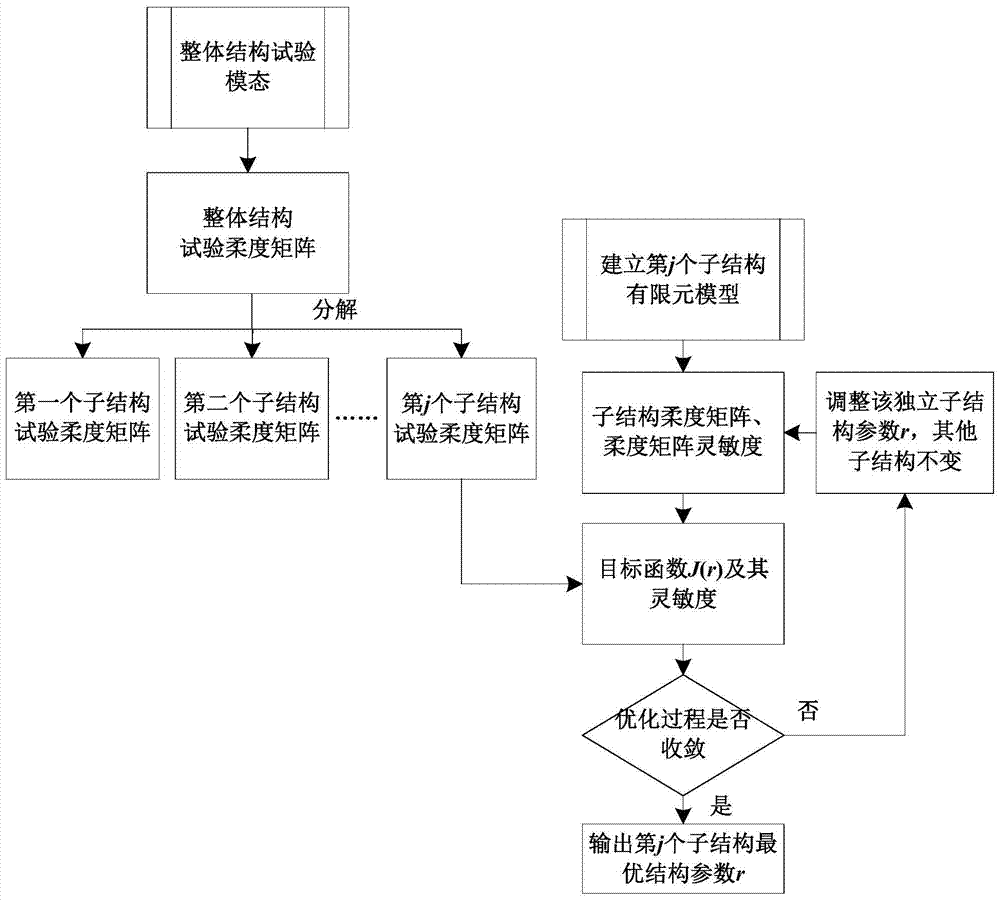
[0069] The specific implementation process of the present invention is as follows figure 1 Shown: First, the overall structure test compliance matrix is ​​extracted from the overall structure test mode; then, the overall structure test mode is decomposed into independent substructures by establishing the connection between the overall structure test compliance matrix and the substructure test co...


PUM


Abstract

The invention discloses a finite element model correction method based on reverse substructure. The method includes the following steps: First, measure the test mode of the actual engineering structure to establish the test mode of the overall structure; through the relationship between the independent substructure test modal parameters and the overall structure test modal parameters, the test mode of the overall structure The mode is decomposed into the test mode of the independent substructure; then, based on the test mode of the independent substructure, the objective function is established, the parameters of the independent substructure are adjusted, the objective function is minimized, and the optimal structural parameters of the substructure are obtained. The optimal structural parameters are used to modify the finite element model of the independent substructure; finally, the structural damage identification is completed according to the changes of the structural parameters of the finite element model before and after the structural damage. The invention avoids repeated analysis of the overall structure model by correcting the independent substructure model, can greatly improve the accuracy and efficiency of the finite element model correction method, and has strong practicability.

Description

technical field [0001] The invention belongs to the technical field of civil engineering large-scale structure detection, and more specifically relates to a method for correcting a finite element model based on an inverse substructure. Background technique [0002] Accurate finite element models are an important basis for structural health assessment and damage identification. Structural health assessment relies to a certain extent on the analysis results of model correction and damage identification. The basic idea of ​​the finite element model correction method is based on the structural test data, and compares the information obtained from the test with the original finite element model analysis results. By optimizing the constraints, the physical parameters of the model (stiffness, mass, size, boundary conditions, etc.) are continuously corrected, so that the theoretical values ​​are basically consistent with the experimental values, so as to identify the physical param...

Claims


Application Information

Patent Timeline
Patent Type & Authority Patents(China)
IPC IPC(8): G06F17/50
Inventor 朱宏平翁顺夏勇毛羚
Owner HUAZHONG UNIV OF SCI & TECH
Why Eureka
Try Eureka