
Touch panel and display device

A touch panel and touch area technology, which is applied in the fields of instruments, electrical digital data processing, and data processing input/output processes, etc., can solve the problems of complex touch structure and large volume of infrared touch panels, and achieve simple structure, High sensitivity and volume reduction effect

Active Publication Date: 2015-03-25
TSD ELECTRONICS TECH
View PDF4 Cites 3 Cited by
  • Summary
  • Abstract
  • Description
  • Claims
  • Application Information

AI Technical Summary

Problems solved by technology

[0006] Therefore, what the present invention aims to solve is the problem of complex touch structure and large volume of the existing infrared touch panel, so as to provide a touch panel with light and thin structure, small volume and high touch sensitivity.

Method used

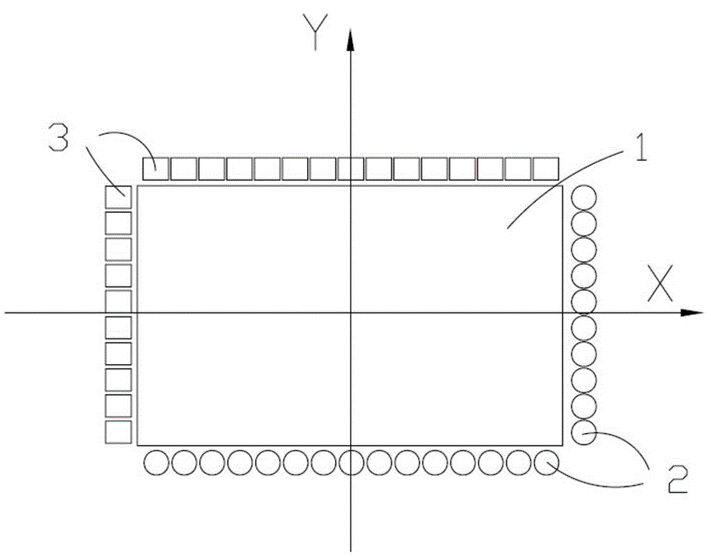
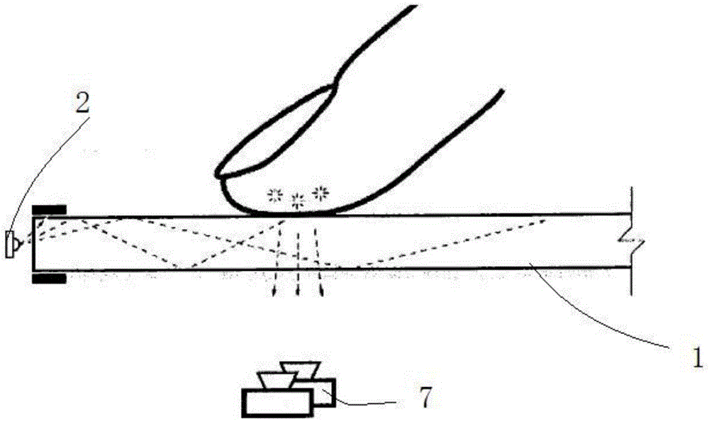

Image

  • Touch panel and display device
  • Touch panel and display device
  • Touch panel and display device

Examples


Embodiment Construction

[0051] In order to make the purpose, technical solution and advantages of the present invention clearer, the following will further describe in detail the embodiments of the present invention in conjunction with the accompanying drawings.

[0052] This invention may be embodied in many different forms and should not be construed as limited to the embodiments set forth herein. Rather, these embodiments are provided so that this disclosure will be thorough and complete and will fully convey the concept of the invention to those skilled in the art, and the present invention will only be defined by the appended claims. In the drawings, the size and relative sizes of layers and regions may be exaggerated for clarity.

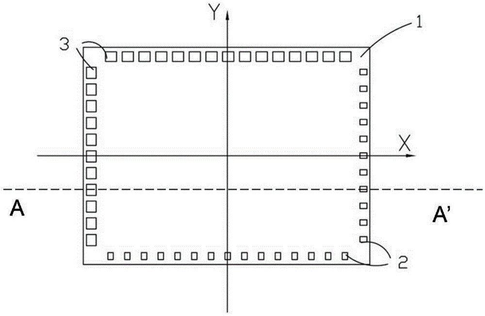
[0053] According to an embodiment of the present invention, a touch panel is provided, such as image 3 As shown, it includes: a transparent substrate 1 , at least one light emitting unit 2 , at least one light receiving unit 3 and a sealing layer 4 . The touch pan...


PUM


Abstract

The invention provides a touch panel and a display device. The touch panel comprises a transparent substrate, at least one light ray emitting unit, a sealing layer and at least one light ray receiving unit. The transparent substrate comprises a first surface and a second surface opposite to the first surface, the first surface and the second surface are used for conducting touching, and the substrate comprises a touch area located in the middle of the substrate and a non-touch area on the periphery of the substrate. The light ray emitting unit is arranged on the non-control area of the second surface and used for emitting light rays including infrared light towards the interior of the substrate. The sealing layer is arranged between the light ray emitting unit and the substrate and used for sealing a light ray outlet face of the light ray emitting unit, the part, away from the light ray outlet face of the light ray emitting unit, of the sealing layer is a plane, and thus light rays are totally reflected in the substrate. The light ray receiving unit is arranged on the non-touch area of the second surface and used for receiving the light rays which are emitted by the light ray emitting unit and pass through the substrate. The connecting line of the light ray emitting unit and the light ray receiving unit transversely penetrates through the touch area.

Description

technical field [0001] The invention relates to the technical field of touch recognition, in particular to a touch panel and a display device. Background technique [0002] Touch panel (English full name is Touch Panel), also known as touch screen and touch screen, is a device that is formed on the display surface of an image display device and uses conductors such as human body or capacitive pen to input commands. It can replace the mouse, keyboard, etc. Input devices such as external input devices and mechanical input keys can effectively simplify the structure of electronic products such as computers, mobile phones, electronic instruments, and game equipment, and have very broad application prospects. [0003] In terms of technical principles, touch panels can be divided into five types: vector pressure sensing touch panels, resistive touch panels, capacitive touch panels, infrared touch panels, and surface acoustic wave touch panels. Existing infrared touch panels such ...

Claims


Application Information

Patent Timeline
Patent Type & Authority Applications(China)
IPC IPC(8): G06F3/042
CPCG06F3/0428G06F2203/04109
Inventor 陈策王志旭徐响林
Owner TSD ELECTRONICS TECH
Learn More