A High Resolution Time Interval Measuring Device with Automatic Correction Function

A time interval, automatic correction technology, applied in the direction of electrical unknown time interval measurement, devices and instruments for measuring time interval, etc., can solve problems such as incomplete elimination, time offset deviation, conversion result gain deviation, etc.

Active Publication Date: 2017-01-25
吉赫科技(东莞)有限公司
View PDF4 Cites 0 Cited by
  • Summary
  • Abstract
  • Description
  • Claims
  • Application Information

AI Technical Summary

Problems solved by technology

[0011] To achieve high-resolution time interval measurement on the order of several picoseconds, a TAC converter with very low noise and low-temperature drift characteristics can be used, but its temperature drift still exists and cannot be completely eliminated. As the temperature is different, the conversion result has a deviation in the gain
In addition, the delay of the digital logic device of the system also changes with the temperature, which brings time offset deviation, so the whole measurement device still has "slow drift".

Method used


Image

  • A High Resolution Time Interval Measuring Device with Automatic Correction Function
  • A High Resolution Time Interval Measuring Device with Automatic Correction Function
  • A High Resolution Time Interval Measuring Device with Automatic Correction Function

Examples


Embodiment Construction

[0038] Specific embodiments of the present invention will be described below in conjunction with the accompanying drawings, so that those skilled in the art can better understand the present invention. It should be noted that in the following description, when detailed descriptions of known functions and designs may dilute the main content of the present invention, these descriptions will be omitted here.

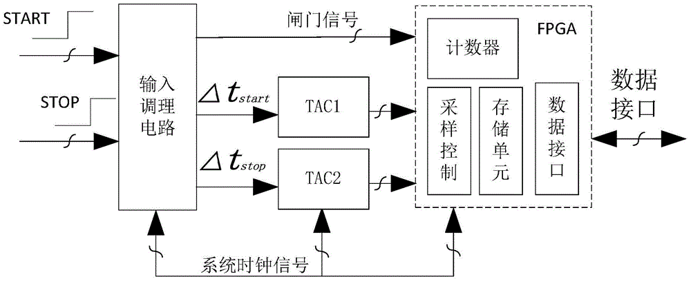
[0039] The input conditioning circuit, time-amplitude converters TAC1, TAC2 and FPGA in the high-resolution time interval measurement device with temperature compensation function of the present invention are all prior art, and will not be repeated here.

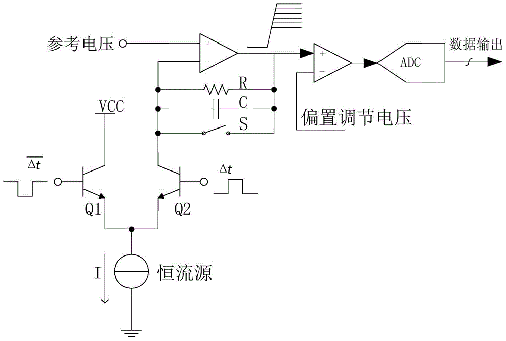
[0040] image 3 It is a schematic diagram of a specific implementation of the automatic correction circuit in the high-resolution time interval measurement device with automatic correction function of the present invention.

[0041] In this example, if image 3 Shown, the automatic correction circuit among the present i...


PUM


Abstract

The high-resolution time interval measurement device with automatic correction function of the present invention adds an automatic correction circuit on the basis of the prior art. The automatic correction circuit generates the correction start signal pulse, the correction stop signal pulse and the system clock, and inputs them into the input conditioning circuit to generate pulse width values ​​of T1 (positive phase clock) and T2 (inverted phase clock) time interval signals Δtstart, Δtstop , time intervals Nstart_1, Nstop_1 (positive-phase clock) and Nstart_2, Nstop_2 (inverted clock) are measured respectively in time-amplitude converters TAC1, TAC2, since the pulse width values ​​T1 and T2 are known, according to these The calculation of the value can offset the influence of the gain coefficient and the delay deviation, thereby correcting the value of the time interval to be measured and further improving the measurement accuracy of the time interval.

Description

technical field [0001] The invention belongs to the technical field of time interval measurement, and more specifically relates to a high-resolution time interval measurement device with an automatic correction function. Background technique [0002] High-resolution time interval measurement technology is widely used in various scientific research and production fields such as electronic instruments, laser ranging, and physical experiments, and is the basic technology in these fields. Currently widely used time interval measurement methods mainly include direct counting method, analog interpolation method, digital vernier method, delay line method and time-amplitude conversion method. [0003] The direct counting method converts the measured signal into a gate signal, controls the high-speed circuit to count the high-speed clock, and obtains the time interval of the measured signal. The principle of this method is relatively simple, but to achieve picosecond-level accuracy,...

Claims


Application Information

Patent Timeline
Patent Type & Authority Patents(China)
IPC IPC(8): G04F10/04
Inventor 邱渡裕叶芃谭峰郭连平程孟曾浩杨扩军黄武煌
Owner 吉赫科技(东莞)有限公司
Why Eureka
Try Eureka