An EUV Lithography Illumination System Based on Freeform Surface Diaphragm Compound Eye

A technology of extreme ultraviolet lithography and aperture compound eye, which is applied in the direction of microlithography exposure equipment, optics, optical components, etc., can solve the problems of affecting the resolution of the exposure system, increasing the difficulty of designing the objective lens system, and reducing the imaging performance of the objective lens system. Achieve the effects of improving resolution, promoting industrial development, and improving energy utilization

Active Publication Date: 2016-04-27
BEIJING INSTITUTE OF TECHNOLOGYGY
View PDF9 Cites 0 Cited by
  • Summary
  • Abstract
  • Description
  • Claims
  • Application Information

AI Technical Summary

Problems solved by technology

However, this structure requires that the diaphragm compound eye be placed directly in the objective lens system. In order to avoid light blocking, the matched objective lens system must reserve enough space to place the diaphragm compound eye during the design process, which greatly increases the cost of the objective lens system. design difficulty; at the same time, this structure requires the illumination system and the objective lens system to be installed in the same vacuum chamber, so that the stray light in the illumination system will significantly reduce the imaging performance of the objective lens system and affect the resolution of the exposure system

Method used


Image

  • An EUV Lithography Illumination System Based on Freeform Surface Diaphragm Compound Eye
  • An EUV Lithography Illumination System Based on Freeform Surface Diaphragm Compound Eye
  • An EUV Lithography Illumination System Based on Freeform Surface Diaphragm Compound Eye

Examples


example 1

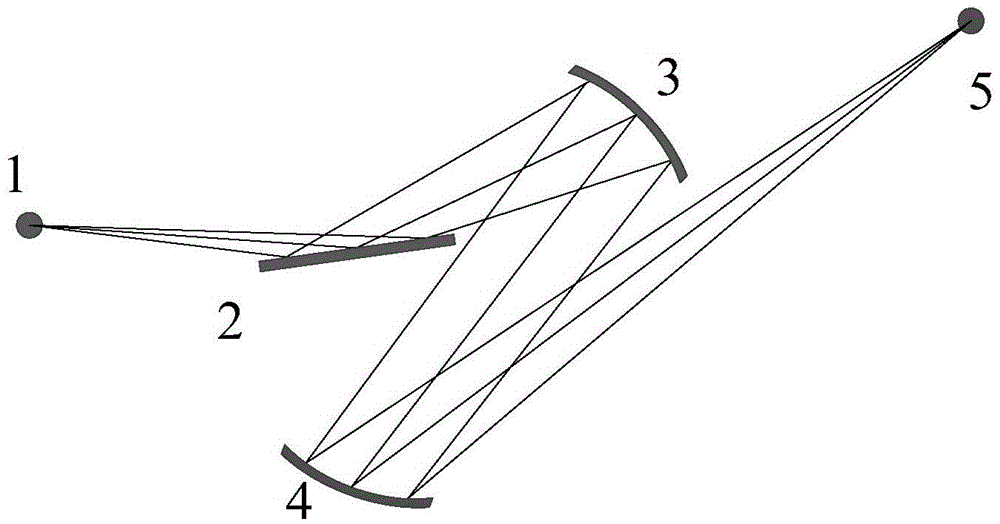
[0032] An extreme ultraviolet lithography illumination system based on a free-form diaphragm compound eye, the system includes a field of view compound eye, a diaphragm compound eye and a quadric mirror;

[0033] The field of view compound eye is composed of several parabolic reflectors. The reflective surface of each parabolic reflector is a rectangle. All the rectangles have the same size. All the field of view compound eyes are closely arranged on the field of view compound eye plate. After the grazing incidence reflection occurs on the compound eye of the field of view, it exits;

[0034] The diaphragm compound eye is composed of several free-form surface mirrors, the reflection surface of each free-form surface mirror is a rectangle, and all the rectangles have the same size, and all the diaphragm compound eyes are arranged on the diaphragm compound eye plate;

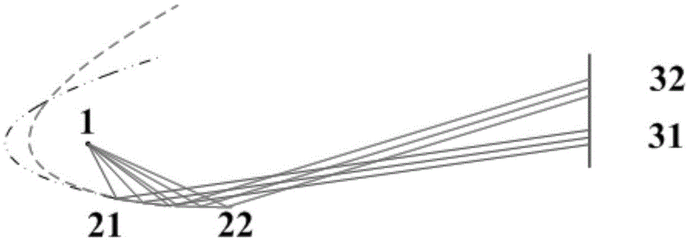
[0035] For the convenience of description, the present invention considers that all light beams exit from the I...

Embodiment

[0043] As shown in Table 1, the exit pupil diameter, the exit pupil distance and the size of the arc-shaped spot on the mask surface of the illumination system are determined for a given set of EUV lithography projection objective lens parameters.

[0044] Table 1

[0045] exit pupil diameter

103.7155mm

Exit pupil distance

1375.5387mm

Arc spot outer diameter

141mm

Inner diameter of arc spot

135mm

Chord length of arc spot

104mm

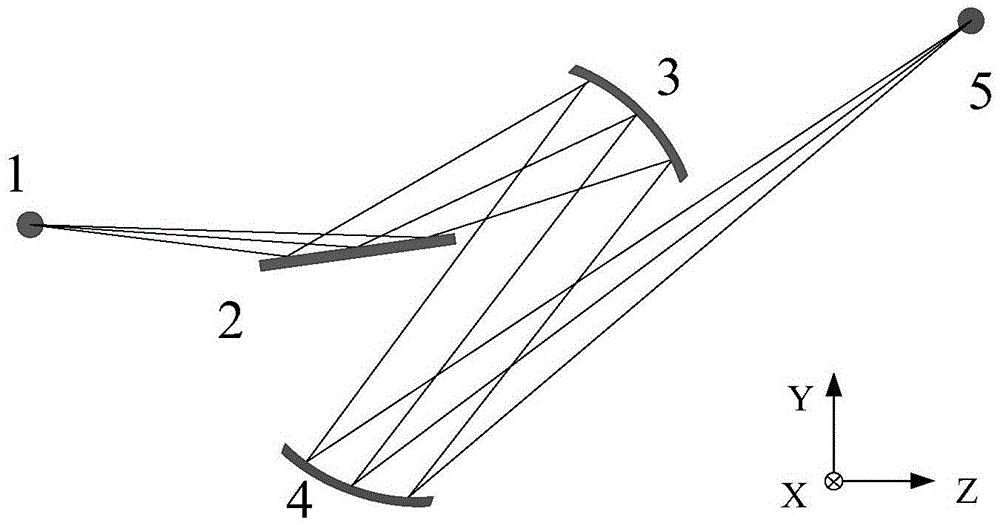
[0046] Establish a Cartesian coordinate system with the IF point as the coordinate origin, the Y axis goes up vertically, the Z axis goes horizontally to the right, and the X axis is determined according to the right-handed coordinate system, such as image 3 shown. The definition of the tilt angle of the component is as follows: the rotation angle of the component around the X axis in the Y-Z plane is defined as alpha, the rotation angle of the component around the Y axis in the X-Z plan...


PUM


Abstract

The invention provides an extreme ultraviolet lithography illuminating system based on a free-form surface diaphragm compound eye. The system comprises a field compound eye, the diaphragm compound eye and a secondary curved surface reflector, wherein the field compound eye consists of multiple parabolic reflectors; incident beams are subjected to grazing incidence on each parabolic reflector, and parallel beams exit to the diaphragm compound eye; the diaphragm compound eye consists of multiple free-form surface reflectors; each free-form surface reflector is used for shaping beams entering the reflector, so that the beams exiting from the diaphragm compound eye form a uniform arc-shaped spot at a specified plane; and the secondary curved surface reflector is used for imaging the arc-shaped spot on a mask surface and imaging the diaphragm compound eye on an entrance pupil surface of a projection objective. The illuminating system consists of three groups of reflectors, and the energy utilization rate of the system is greatly improved. Meanwhile, the system adopts the free-form surface diaphragm compound eye, so that the uniform arc-shaped spot meeting the requirement is obtained on the mask surface.

Description

technical field [0001] The invention provides an extreme ultraviolet lithography illumination system based on a free-form surface diaphragm compound eye, belonging to the technical field of lithography illumination. Background technique [0002] As one of the next-generation lithography technologies, extreme ultraviolet (EUV) lithography is expected to meet the industrialization requirements of semiconductor manufacturing at 22nm and higher technology nodes. The core components of a projection lithography machine include a light source, an illumination system, and a projection objective lens system. The main function of the illumination system is to provide uniform illumination for the mask surface, control the exposure dose and realize various illumination modes. At present, there are two main design ideas of extreme ultraviolet lithography lighting system: double-row compound-eye lighting based on Kohler lighting and corrugated plate lighting based on Kohler-critical ligh...

Claims


Application Information

Patent Timeline
Patent Type & Authority Patents(China)
IPC IPC(8): G03F7/20G02B17/06G21K1/06
Inventor 李艳秋梅秋丽
Owner BEIJING INSTITUTE OF TECHNOLOGYGY
Why Eureka
Try Eureka