Illuminating system of imaging flow cytometry

A flow cytometer and lighting system technology, applied in the field of optical design, can solve the problems of optical-mechanical design constraints, high development costs, and large light energy loss, so as to avoid constraints, solve development problems, and reduce light energy loss. Effect

Inactive Publication Date: 2015-03-25
CHANGCHUN INST OF OPTICS FINE MECHANICS & PHYSICS CHINESE ACAD OF SCI
View PDF4 Cites 4 Cited by
  • Summary
  • Abstract
  • Description
  • Claims
  • Application Information

AI Technical Summary

Problems solved by technology

[0004] The purpose of the present invention is to propose a lighting system for imaging flow cytometers, which solves the problems of large loss of light energy, low utilization rate, high development cost, poor stability and certain restrictions on the design of light machines in the prior art.

Method used


Image

  • Illuminating system of imaging flow cytometry
  • Illuminating system of imaging flow cytometry
  • Illuminating system of imaging flow cytometry

Examples


Embodiment Construction

[0014] Embodiments of the present invention will be further described below in conjunction with the accompanying drawings.

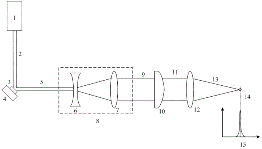
[0015] See attached figure 1 , the illumination system of the imaging flow cytometer of the present invention includes a laser light source 1, a digital micromirror array 3, a piezoelectric ceramic rotating platform 4, a laser beam expander system 8, a cylindrical mirror 10 and a focusing lens 12;

[0016] The fundamental mode light 2 output by the laser light source 1 passes through the digital micromirror array 3 to generate the reflected light 5, and the reflected light 5 is expanded by the laser beam expander system 8 to form the expanded beam 9 of the circular spot. Due to the change of the image size of the cylindrical mirror 10 application, the beam expanding light 9 is imaged into an elliptical spot 11 by a cylindrical mirror 10, and the focused ray 13 generated by the focusing lens 12 by the elliptical spot 11 is focused into a uniform beam at t...


PUM


Abstract

The invention discloses an illuminating system of an imaging flow cytometry and belongs to the technical field of optical design. The system aims to solve the problems of the prior art that optical energy loss is high, utilization rate is low, researching and manufacturing cost is high, stability is poor, and the design of a beam-focusing machine is limited to a certain extent. The system comprises a laser light source, a digital micro mirror array, a piezoelectric ceramics tilt platform, a laser expanding system, a cylindrical mirror and a focusing lens, wherein basic mode light rays output by the laser light source become reflection light rays through the digital micro mirror array, the reflection light rays are expanded through the laser expanding system to form round spot expanded light rays, the expanded light rays are imaged to be oval light spots through the cylindrical mirror, the oval light spots become focused light rays through the focusing lens, the focused light rays are focused into a uniform linear light spot at the position of a target surface, and the digital micro mirror array is arranged on the piezoelectric ceramics tilt platform and achieves high-speed scanning under the control of the piezoelectric ceramics tilt platform.

Description

technical field [0001] The invention belongs to the technical field of optical design, and in particular relates to an illumination system for detection equipment such as an imaging flow cytometer. Background technique [0002] During the development of imaging flow cytometer, high brightness and uniform requirements are put forward for its illumination system. The fundamental mode laser light source (TEM00) with outstanding characteristics such as high brightness, monochromaticity, and coherence has become the most suitable choice. In order to uniformly irradiate the cells and improve the resolution, the diameter of the laser spot irradiated on the cells should be similar to the diameter of the cells. Therefore, the intensity distribution of the laser light used for illumination is required to be flat-topped like a rectangular pulse. [0003] In order to form a flat-top light intensity distribution on the target surface, the illumination system in the current imaging flow...

Claims


Application Information

Patent Timeline
Patent Type & Authority Applications(China)
IPC IPC(8): G02B26/10G02B27/09
Inventor 刘华党博石卢振武孙强赵建
Owner CHANGCHUN INST OF OPTICS FINE MECHANICS & PHYSICS CHINESE ACAD OF SCI
Why Eureka
Try Eureka