
High-power plane heating unit liquid-cooling heat dissipating device and manufacturing method thereof

A technology of flat heating and heat dissipation device, applied in cooling/ventilation/heating renovation, indirect heat exchanger, lighting and heating equipment, etc., to achieve the effect of high integration, excellent heat exchange effect and flexible installation method

Inactive Publication Date: 2015-03-25
HANGZHOU JIASEN TECH
View PDF9 Cites 7 Cited by
  • Summary
  • Abstract
  • Description
  • Claims
  • Application Information

AI Technical Summary

Problems solved by technology

[0002] At present, generally high-power heating elements adopt liquid cooling to dissipate heat, such as power modules and various semiconductor heating elements, but the shapes of various heating elements are different, and there are different requirements for the size of the radiator, especially some high-power semiconductor lighting The shape of equipment, such as high-power LEDs, is ever-changing, so there are also different requirements for the size of the radiator. How to quickly and cost-effectively manufacture a heat dissipation component of an appropriate size is a problem that currently exists
[0003] CN201210532398 patent discloses a cooling system suitable for high-power LED lamps, including a radiator and a water-cooled driving device. The radiator is a columnar structure with a cavity. One end of the radiator is provided with a liquid inlet, and the other end is provided with a One liquid outlet; the water-cooled driving device is connected to the liquid inlet and outlet of the radiator through water pipes or only connected to the liquid inlet of the water-cooled driving device; although the heat dissipation system has good heat dissipation effect, energy saving, low cost, safety and environmental protection and other advantages, but because the radiator is a fixed shape, it can only be applied to heating equipment whose shape and size are compatible with it

Method used


Image

  • High-power plane heating unit liquid-cooling heat dissipating device and manufacturing method thereof
  • High-power plane heating unit liquid-cooling heat dissipating device and manufacturing method thereof
  • High-power plane heating unit liquid-cooling heat dissipating device and manufacturing method thereof

Examples


Embodiment Construction

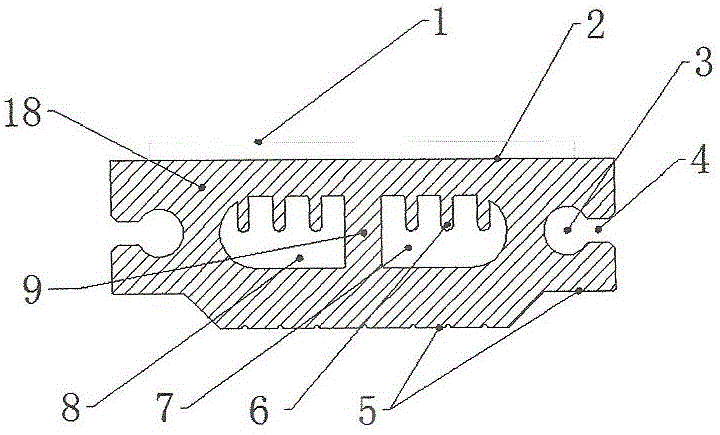
[0028] Such as figure 1 The cross-sectional view of the heat dissipation profile shown and figure 2 , Figure 6 and Figure 10 It can be seen that the heat dissipation device includes a cooling liquid driving device 14 and a radiator 13, and the cooling liquid driving device is provided with a liquid inlet 15 and a liquid outlet 16, and is respectively connected with a liquid outlet provided on the radiator through a pipeline 17. The port 11 is connected with the liquid inlet 10 to form a cooling circulation system. The radiator 13 is composed of a section of heat dissipation profile 18 and a sealing block 12 installed at both ends of the heat dissipation profile. The upper surface is the heat dissipation surface 2 for installing a plane heating element , the lower surface is the mounting surface 5 for accessories installation, the inside of the heat dissipation profile 18 is provided with a cooling liquid channel and an installation channel 3 for wiring, and a partition 9 ...


PUM


Abstract

The invention discloses a high-power plane heating unit liquid-cooling heat dissipating device which comprises a cooling liquid driving device (14) and a heat dissipator (13). The heat dissipator (13) is composed of a heat dissipating sectional material (18) and sealing plug blocks (12), the heat dissipating sectional material (18) is a flat-section structure with cavities, a heat dissipating face (2) and mounting faces (5) used for mounting of a plane heating unit are arranged on the surface of the heat dissipating sectional material (18), cooling liquid channels and mounting pipelines (3) are arranged inside the heat dissipating sectional material (18), and a liquid inlet (10) and a liquid outlet (11) of the heat dissipator are communicated with the cooling liquid channels. By adoption of the structure, the heat dissipating sectional material is formed at a time, can be cut according to the shape of the plane heating unit and can be provided with the liquid inlet and the liquid outlet at different positions, heat dissipating devices of different heat dissipating structures can be manufactured only through simple machining, multiple heat dissipators can be assembled in parallel to be matched with the width of the plane heating unit, and heat dissipating requirements of the plane heating units in different shapes are met.

Description

technical field [0001] The invention relates to a device for heat dissipation of a high-power planar heating body, which can conveniently implement liquid cooling to solve the problem of heat dissipation of a high-power heating planar body. Planar heating elements usually include CPU, PTC cooling chips, high-power semiconductor lighting equipment, special-purpose lighting equipment, built-in power supply modules, backlight module modules, and heating power devices of electronic equipment (integrated circuits, thyristors, transformers, power supply modules) A heating element with a flat contact surface. Background technique [0002] At present, generally high-power heating elements adopt liquid cooling to dissipate heat, such as power modules and various semiconductor heating elements, but the shapes of various heating elements are different, and there are different requirements for the size of the radiator, especially some high-power semiconductor lighting The shapes of equ...

Claims


Application Information

Patent Timeline
IPC IPC(8): F28D15/00H05K7/20B23P15/26
Inventor 金东
Owner HANGZHOU JIASEN TECH
Learn More