
Plunger pump

A plunger pump and plunger technology, applied in the field of plunger pumps, can solve the problems that the displacement of the plunger pump cannot be adjusted, and achieve the effect of prolonging the service life

Active Publication Date: 2015-03-25
CHINA TOBACCO GUIZHOU IND
View PDF8 Cites 1 Cited by
  • Summary
  • Abstract
  • Description
  • Claims
  • Application Information

AI Technical Summary

Problems solved by technology

[0004] In view of the shortcomings of the prior art described above, the purpose of the present invention is to provide a plunger pump for solving the problem that the displacement of the plunger pump in the prior art cannot be adjusted

Method used


Image

  • Plunger pump
  • Plunger pump
  • Plunger pump

Examples


Embodiment Construction

[0028] The implementation of the present invention will be illustrated by specific specific examples below, and those skilled in the art can easily understand other advantages and effects of the present invention from the contents disclosed in this specification.

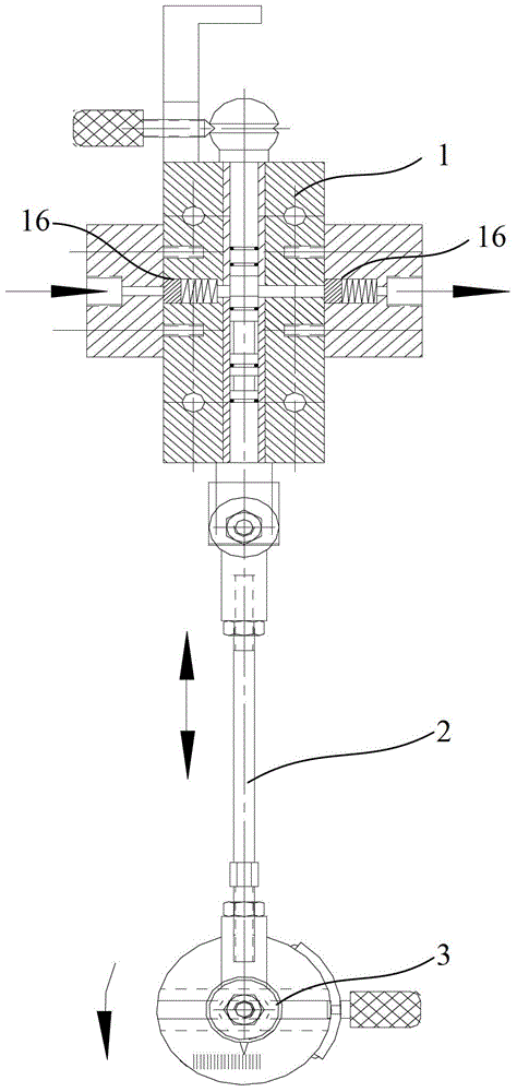
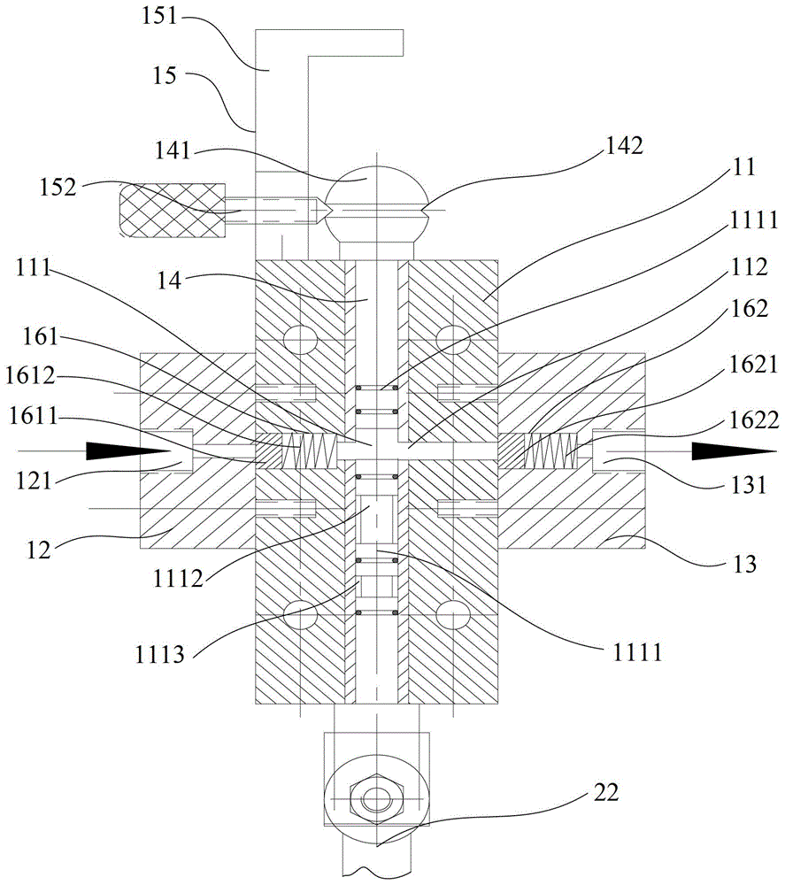
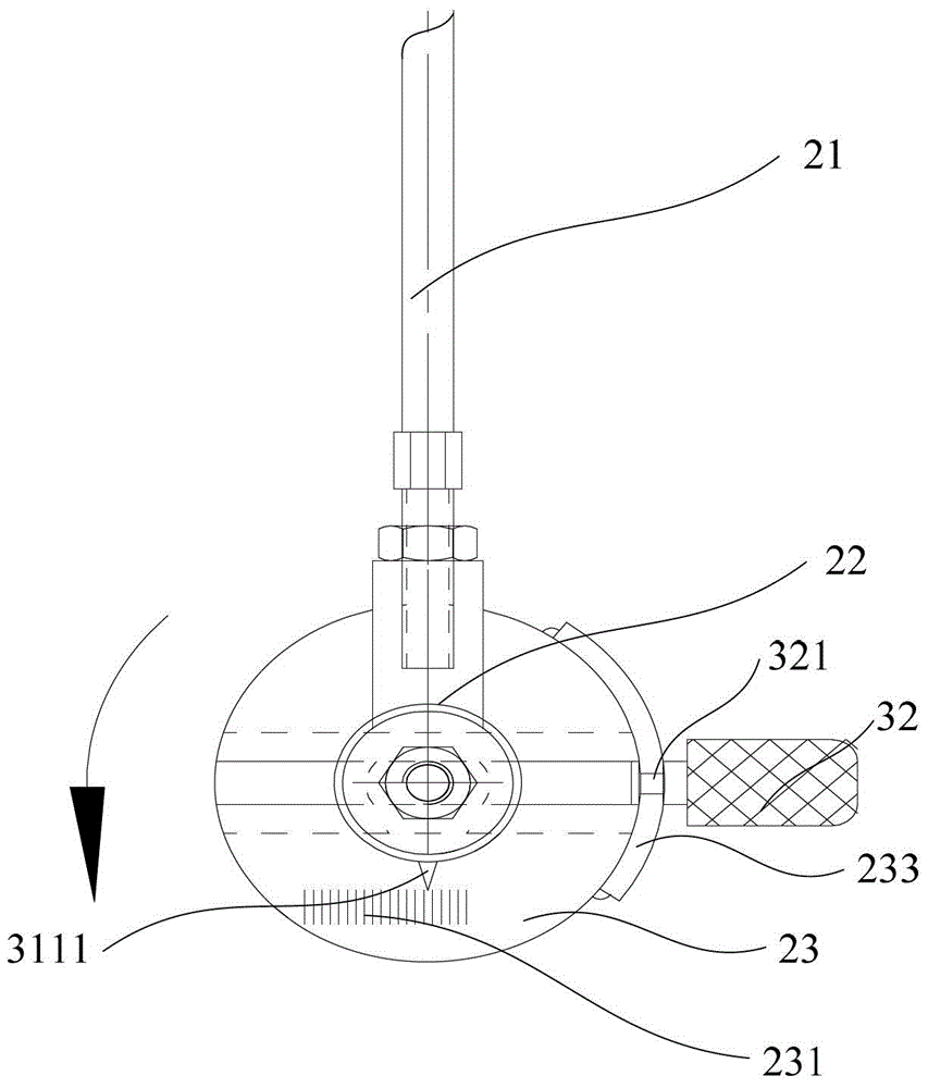
[0029] see Figure 1 to Figure 6 . It should be noted that the structures, proportions, sizes, etc. shown in the drawings attached to this specification are only used to match the content disclosed in the specification, for those who are familiar with this technology to understand and read, and are not used to limit the implementation of the present invention. Limiting conditions, so there is no technical substantive meaning, any modification of structure, change of proportional relationship or adjustment of size, without affecting the effect and purpose of the present invention, should still fall within the scope of the present invention. The disclosed technical content must be within the scope covered. At the sa...


PUM


Abstract

The invention provides a plunger pump. The plunger pump comprises a valve body, a drive transfer portion and a displacement regulating portion. The valve body consists of a main valve body, a left valve body and a right valve body, the valve body is provided with a fluid flow passage communicated with an oil inlet and an oil outlet, flow-limiting valves for controlling the oil inlet and the oil outlet to open and close are arranged in the fluid flow passage, the main valve body is provided with a hermetic hydraulic cavity communicated with the fluid flow passage, and a plunger is arranged in the hydraulic cavity. The drive transfer portion comprises a connecting rod and a regulating seat, the upper end of the connecting rod is hinged to the bottom end of the plunger, and the lower end of the connecting rod is hinged to the regulating seat. The displacement regulating portion is arranged in the regulating seat and comprises a regulating block, a hinge joint shaft and a regulating drive part, wherein the regulating block is embedded into the regulating seat, the hinge joint shaft is fixedly connected to the regulating block, and the regulating drive part is used for regulating the position of the hinge joint shaft. The plunger pump is capable of providing precise displacement according to different displacement needs.

Description

technical field [0001] The invention relates to a pump, in particular to a plunger pump. Background technique [0002] The plunger pump is a positive displacement pump, which is driven by an electric motor and connected to the piston rod through a reduction box and a crank connecting rod mechanism to make the piston reciprocate. It relies on the reciprocating movement of the piston and sequentially opens the suction valve and the discharge valve to suck in and discharge the liquid. Its working principle is: with the reciprocating movement of the piston, when the volume of the working chamber increases, a low pressure is formed, and the liquid in the liquid storage tank can be sucked into the pump cylinder through the suction valve. When the liquid is sucked, the discharge valve is closed due to the liquid pressure in the discharge pipe. Afterwards, when the volume of the working chamber decreases, the liquid in the pump cylinder is squeezed to increase its pressure, so tha...

Claims


Application Information

Patent Timeline
Patent Type & Authority Applications(China)
IPC IPC(8): F04B53/10F04B53/00
Inventor 周红光聂长春阮家强惠建权冯勇徐忠平黄杰张明亚翟义龙
Owner CHINA TOBACCO GUIZHOU IND
Learn More