
Synchronous oil supply and hold-down device for detecting high-pressure common-rail oil sprayer online and application method thereof

A common rail fuel injector and high pressure common rail technology, which is applied in the testing of measuring devices, fuel injection devices, and machine/structural components, etc., can solve the problem of low stability and reliability, oil leakage on the sealing surface, and affecting the sealing effect. and other problems, to achieve the effect of improving reliability and authenticity, improving high-pressure sealing performance, and improving detection efficiency

Active Publication Date: 2015-03-25
常州博瑞油泵油嘴有限公司
View PDF9 Cites 9 Cited by
  • Summary
  • Abstract
  • Description
  • Claims
  • Application Information

AI Technical Summary

Problems solved by technology

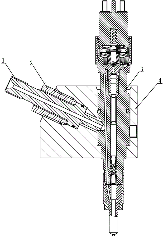
[0006] 1) It takes a lot of auxiliary time to install and disassemble, the detection efficiency is low, and the detection cost is high: the high-pressure oil injection joint is tightly sealed with the oil inlet joint of the fuel injector through the screw cap. At present, the test time of the fuel injector assembly takes 3 minutes, of which , the test time of the whole fuel injector is only 45 seconds, and the rest of the time is used for installation and disassembly, so it can be seen that 75% of the time required for fuel injector performance testing is consumed in the installation and disassembly of the fuel injector. Affects the speed of online inspection, inspection and production are out of sync, must increase inspection equipment and personnel, and the inspection cost is high
[0007] 2) The stability and reliability of the detection is not high: the high-pressure oil injection joint is tightly sealed by screwing the nut and the oil inlet joint of the injector. The performance of the seal depends on the tightening torque of the nut, which is affected by the operator's human factors , the operator completes the tightening with a wrench. Due to different workers or different methods of tightening, the actual axial force is inconsistent and the difference is large.
If the force is too strong, it will damage the sealing surface of the injector, and even affect the deformation of the oil passage of the injector, resulting in throttling and affecting the test accuracy; if the force is too light, it will cause oil leakage on the sealing surface, resulting in the failure of the injector. The actual working pressure is low, which will also affect the test accuracy;
[0008] 3) The high-pressure oil injection joint is screwed and sealed with the oil inlet joint of the injector through the nut, which may easily cause the injector to fail. Since the nut is easy to drive the oil injection joint to rotate when the nut is tightened, if the oil injection joint and the taper hole of the injector are along the axis If there is relative movement in the direction of rotation, burrs are likely to occur on the joint surface, which affects the sealing effect. In serious cases, the burrs will enter the oil passage of the injector and cause the injector to fail

Method used


Image

  • Synchronous oil supply and hold-down device for detecting high-pressure common-rail oil sprayer online and application method thereof
  • Synchronous oil supply and hold-down device for detecting high-pressure common-rail oil sprayer online and application method thereof
  • Synchronous oil supply and hold-down device for detecting high-pressure common-rail oil sprayer online and application method thereof

Examples


specific Embodiment approach

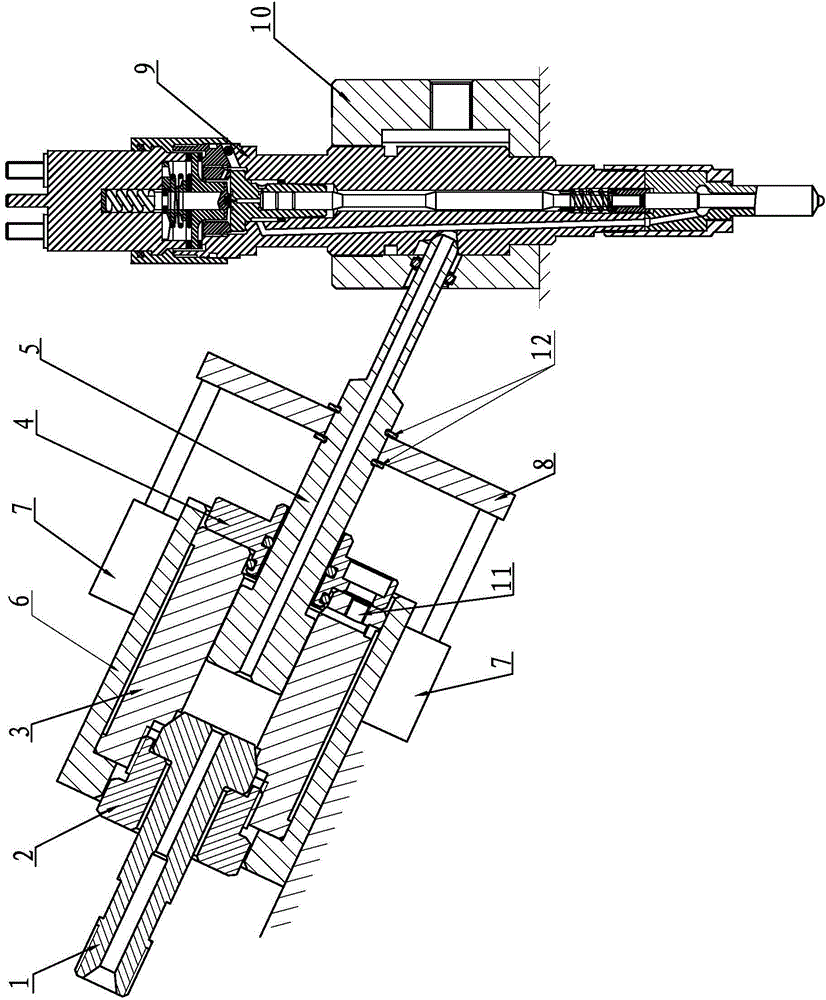
[0024] A high-pressure common rail injector online detection synchronous oil supply and pressing device, such as figure 2 and image 3 As shown, it includes high-pressure oil injection joint 1, fastening nut sleeve 2, piston sleeve 3, pressure relief end cover 4, oil injection piston 5, fixed seat sleeve 6, cylinder 7, connecting plate 8, common rail injector to be inspected 9 and the injector installation sleeve 10, the high-pressure oil injection joint 1 is hermetically installed on the oil inlet end of the piston sleeve 3 through the fastening nut sleeve 2, and the oil injection piston 5 is provided with a stepped structure of an oil delivery hole 51 at the center, which consists of the first A guide section 52, a second guide section 53 and a butt joint 54 are composed. The first guide section 52 is set in the inner hole of the piston sleeve 3, the pressure relief end cap 4 is set on the second guide section 53, and the pressure relief end cover 4 Fixed on the piston sle...


PUM


Abstract

The invention provides a synchronous oil supply and hold-down device for detecting a high-pressure common-rail oil sprayer online. The synchronous oil supply and hold-down device comprises a high-pressure oil supply and sealing butt joint component and a preliminary butt joint and disengagement mechanism, wherein the high-pressure oil supply and sealing butt joint component is composed of a high-pressure oil injection connector, a fastening nut sleeve, a piston sleeve, a pressure relief end cover and an oil injection piston, and the preliminary butt joint and disengagement mechanism is composed of a fixed socket sleeve, an air cylinder and a connecting plate. The common-rail oil sprayer is perpendicularly mounted on an oil sprayer mounting sleeve in a sleeved mode. The axis of an oil inlet taper hole of the common-rail oil sprayer and the axis of the oil injection piston are collinear. Since the synchronous oil supply and hold-down device is used for detecting the common-rail oil sprayer online, the detection time is shortened from existing three minutes per piece to 55 seconds per piece, the auxiliary time is shortened from existing 135 seconds to 10 seconds, and benefits are remarkable. In the force application process, the oil injection piston will not rotate in the axial direction, the surface of the oil injection piston will not be scratched, and the oil injection piston can also be prevented from getting stuck. In the operating process, high-pressure oil leaks through a gap between the oil injection piston and the piston sleeve, and the leaked fuel oil can be collected by the pressure relief end cover and led back to an oil tank, so the utilization rate of the fuel oil and the cleanliness of a working table are guaranteed.

Description

Technical field: [0001] The invention relates to a performance detection technology of a high-pressure common rail fuel injector assembly of a diesel engine, in particular to a synchronous oil supply and clamping device for online detection of a high-pressure common rail fuel injector assembly. Background technique: [0002] With the progress of society, the requirements for energy saving and emission reduction of diesel engines are getting higher and higher; this puts forward new requirements for the fuel supply system of diesel engines, requiring them to provide higher pressure fuel with more accurate timing and injection volume; With the development of technology, people have reached a consensus that the common rail system is currently the only fuel supply system that can meet the above three requirements at the same time. [0003] The function of the common rail injector is to control the opening and closing of the high-speed solenoid valve through the electronic control...

Claims


Application Information

Patent Timeline
IPC IPC(8): F02M51/06F02M61/10F02M65/00
Inventor 鞠得雨庄福如汤曌蒋岳群钱亚庆蒋辉
Owner 常州博瑞油泵油嘴有限公司
Learn More