Eureka AIR delivers breakthrough ideas for toughest innovation challenges, trusted by R&D personnel around the world.

Oil sprayer

A technology of fuel injectors and injection bases, which is applied in the direction of machines/engines, fuel injection devices, engine components, etc., can solve the problems of increased processing difficulty, slow heat loss, complex structure, etc., to achieve reduced residue or solidification, and low processing difficulty , good fluidity effect

Active Publication Date: 2015-03-25
CHINA FAW LIMITED WUXI FUEL INJECTIONEQUIP RES INST +1
View PDF9 Cites 8 Cited by
  • Summary
  • Abstract
  • Description
  • Claims
  • Application Information

AI Technical Summary

Problems solved by technology

However, on the one hand, the angular position of the above-mentioned lateral through holes may affect the flow of fuel at the head of the valve seat, and the structure is more complicated, which increases the difficulty of processing
On the other hand, there is no vertical passage of fuel inside the guide, the cooling effect of the guide is poor, the heat dissipation is slow, and there is still fuel residue near the nozzle hole
At the same time, the structural design of the guide also brings another problem. Since the oil passage between the guide and the injector housing is the main oil passage of the fuel, the wall thickness of the guide is relatively thin, and the guide The guiding part of the guide part is relatively short. When the guide part and the shell are welded and assembled, the contact part between the guide part and the shell is prone to thermal deformation, and even the deformation of the ball head of the guide part will be caused, which will cause oil injection. The device works unstable

Method used


Image

  • Oil sprayer
  • Oil sprayer
  • Oil sprayer

Examples


Embodiment 1

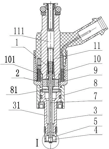
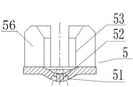
[0029] Embodiment 1: As shown in 4, there are four slots 54, and every two slots 54 are orthogonal to each other.

Embodiment 2

[0030] Embodiment two: if Figure 5 and Figure 6 As shown, there are three slots 54, and the angle between every two slots 54 is 120°.

[0031] The above-mentioned slots 54 that are orthogonal to each other or at an angle of 120° work together with the annular inner surface 53 of the valve wall 56 to form a connected fuel inner passage. The width of the slots 54 is as wide as possible to expand the volume of the fuel passage , so as to reduce the fluid resistance and improve the heat dissipation effect of these parts, but in order to ensure its guiding effect on the ball head 4, the width of the slot 54 should be smaller than the diameter of the ball head 4. The annular inner surface 53 of the valve wall 56 acts as a guide for the ball head 4 . The outer peripheral surface of the valve wall 56 has a certain guiding effect on the inner peripheral surface of the needle valve body 3, which can ensure that when the valve seat 5 and the needle valve body 3 are welded and a...


PUM


Abstract

The invention discloses an oil sprayer which comprises a valve rod, a ball head and an oil sprayer component for controlling the valve rod to axially move between an opening position and a closing position, wherein a valve seat is arranged on the outer side of the ball head, and comprises a valve wall and a spraying base, which are integrated; a needle valve body is arranged on the outer side of the valve wall; the valve wall is provided with an annular inner surface for the axial movement of the ball head; a plurality of nozzle holes are formed in the spraying base; a sealing surface capable of sealing all the nozzle holes is arranged between the inner lateral surface of the spraying base and the bottom of the ball head; the valve wall is circumferentially and uniformly provided with a plurality of radially through straight slots. With the adoption of such a structure, the spraying performance of a direct oil sprayer in a gasoline cylinder can be achieved; meanwhile, an outer fuel passage and the straight slots are formed, so that high flowing property of a fuel can be achieved, and the inner and outer surfaces of the valve seat are wetted by the fuel all the time to achieve lower temperature of the valve seat and reduce the remaining or curing of the fuel in the vicinity of the nozzle holes of the oil sprayer.

Description

technical field [0001] The invention relates to a fuel injection system used in an automobile internal combustion engine, in particular to a fuel injector. Background technique [0002] Fuel is ejected from the nozzle hole of the injector, and a certain amount of fuel adheres around the nozzle hole. These residual fuels are solidified by the heating of the surrounding environment, accumulate around the nozzle and even block the nozzle hole, the spray direction of the fuel sprayed through the nozzle hole and the shape of the fuel spray may change, thereby affecting the injection characteristics of the injector, eventually causing The engine experienced sluggish acceleration, jerky idling, and loss of power. Therefore, it is necessary to prevent fuel residue or solidification as much as possible, so as to realize the ideal injection characteristics of the injector. [0003] In order to prevent the fuel injected by the injector from remaining around the nozzle hole, most of t...

Claims


Application Information

Patent Timeline
IPC IPC(8): F02M51/06F02M61/06
Inventor 宋睿智李丽夏少华居钰生房志红袁亚飞
Owner CHINA FAW LIMITED WUXI FUEL INJECTIONEQUIP RES INST
Why Eureka
Eureka Blog
Learn More