
Oil injection combustion-supporting regeneration temperature control method for DPF diesel engine particle filter system

A particle filtration and regeneration temperature technology, applied in mechanical equipment, engine components, combustion engines, etc., can solve problems affecting regeneration efficiency, incomplete combustion of soot particles, damage to DPF diesel engine particle filter system, etc., and achieve the effect of avoiding aging

Active Publication Date: 2015-03-25
KAILONG HIGH TECH
View PDF6 Cites 35 Cited by
  • Summary
  • Abstract
  • Description
  • Claims
  • Application Information

AI Technical Summary

Problems solved by technology

In the traditional DPF diesel engine particle filter system fuel injection combustion-supporting regeneration technology, the temperature control in the regeneration process is only through a single PID (Proportion Integration Differentiation, proportional integral differential) closed-loop control, which is easy to cause the temperature value to be too high or too low, and the temperature value is too low It will lead to incomplete combustion of soot particles accumulated in the DPF filter, which will affect the regeneration efficiency; too high temperature value will easily cause damage to the DPF diesel engine particulate filter system

Method used


Image

  • Oil injection combustion-supporting regeneration temperature control method for DPF diesel engine particle filter system
  • Oil injection combustion-supporting regeneration temperature control method for DPF diesel engine particle filter system

Examples


Embodiment Construction

[0026] The present invention will be further described below in conjunction with drawings and embodiments. It should be understood that the specific embodiments described here are only used to explain the present invention, but not to limit the present invention. In addition, it should be noted that, for the convenience of description, only parts related to the present invention are shown in the drawings but not all content.

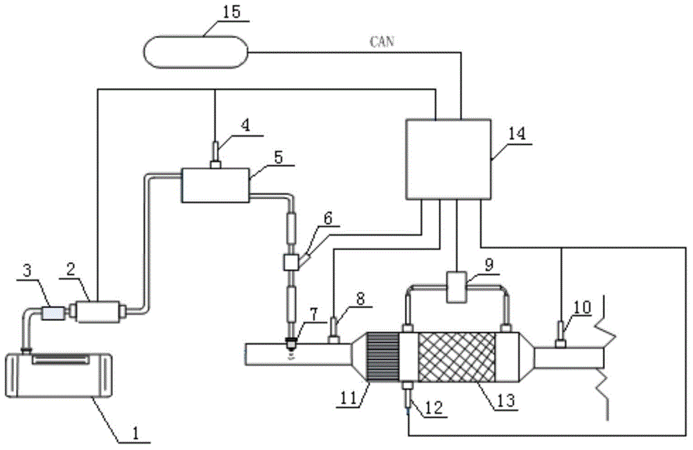
[0027] Please refer to figure 1 as shown, figure 1 It is a structural diagram of a DPF diesel particulate filter system provided by an embodiment of the present invention.

[0028] In this embodiment, the DPF diesel particulate filter system adopts the technology of combining DOC and DPF, including: fuel tank 1, fuel pump 2, filter 3, pressure sensor 4, pressure accumulator chamber 5, fuel control valve 6, nozzle 7, DOC Temperature sensor 8 at the air inlet of the catalyst, differential pressure sensor 9, temperature sensor 10, DOC catalyst 11, temper...


PUM


Abstract

The invention discloses an oil injection combustion-supporting regeneration temperature control method for a DPF diesel engine particle filter system. The method comprises the steps that a DPF system temperature numerical value is collected through a temperature sensor in real time and transmitted to an electronic control unit, the electronic control unit is used for working out the fuel injection amount needed for adjusting the current temperature of a DPF into a target temperature through an open loop control algorithm and a closed loop PID control algorithm according to the temperature numerical value and transforming the fuel injection amount into a corresponding pulse width signal to drive a fuel control valve, the accurate control over the current fuel injection amount of a DOC catalyst is achieved, the exhaust temperature of an engine is controlled, and thus the temperature of the DPF is controlled. According to the method, the amount of fuel injected by the fuel control valve is controlled through open loop control and closed loop control, the flexible variable control over the temperature of the DPF diesel engine particle filter system in the regeneration process is achieved, it can be ensured that smoke particles captured in the DPF are combusted, and the phenomenon that the regeneration temperature is out of control, and consequently the DPF diesel engine particle filter system is aged and damaged can be avoided.

Description

technical field [0001] The invention relates to the technical field of exhaust post-treatment of internal combustion engines, in particular to a temperature control method for fuel injection and combustion-supporting regeneration of a DPF diesel engine particulate filter system. Background technique [0002] Soot particles are one of the most important pollutants in diesel engine exhaust emissions. DPF (Diesel Particulate Fitter, Diesel Particulate Filter) diesel particulate filter system is currently the most effective device for reducing diesel engine soot particle emissions. However, as the working time increases, more and more soot particles accumulate in the DPF diesel particulate filter system, which not only affects the capture effect, but also causes incomplete combustion of engine fuel. Special measures are required to capture the DPF diesel particulate filter system. Soot particles are removed to achieve DPF regeneration. Among many regeneration methods, the fuel ...

Claims


Application Information

Patent Timeline
IPC IPC(8): F01N3/025F01N11/00
CPCY02T10/40
Inventor 臧志成
Owner KAILONG HIGH TECH
Learn More