
Acoustic logging while drilling method and device based on double-source flyback technology

A sonic and logging technology, applied in the field of sonic logging while drilling methods and devices, can solve problems such as drill collar wave interference, achieve the effects of reducing maintenance costs, avoiding groove design, and avoiding damage

Active Publication Date: 2015-03-25
CHINA UNIV OF PETROLEUM (EAST CHINA)
View PDF6 Cites 10 Cited by
  • Summary
  • Abstract
  • Description
  • Claims
  • Application Information

AI Technical Summary

Problems solved by technology

[0007] The purpose of the present invention is to provide a method and device for acoustic logging while drilling based on dual-source flyback technology, so as to solve the interference problem of drill collar waves during single-pole longitudinal wave logging while drilling. The link suppresses the drill collar wave to improve the signal-to-noise ratio of the formation wave, and adopts the data processing method of acoustic wave interferometry in subsequent data processing, thus forming an acoustic logging while drilling technology that does not require sound insulation devices

Method used


Image

  • Acoustic logging while drilling method and device based on double-source flyback technology
  • Acoustic logging while drilling method and device based on double-source flyback technology
  • Acoustic logging while drilling method and device based on double-source flyback technology

Examples


Embodiment Construction

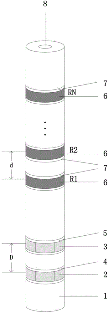
[0037] The acoustic logging while drilling tool based on dual-source flyback technology such as figure 1 Shown. It mainly includes the sound system part and the circuit part (both are embedded in the drill collar). The sound system is like figure 1 As shown, it is composed of dual-source transmitting and receiving arrays. In the figure, 1 is the drill collar, 2 and 3 are the remote transmitter T f , Near transmitter T n , Are two monopole piezoelectric transducers with the same working performance, which can emit sound waves to the formation under the excitation of the high voltage of the transmitting circuit. 4 and 5 are far-emitting and near-emitting sound-transmitting covers respectively. The main function is to protect the transmitter Energy sensor and sound transmission; 6 is a monopole receiving array composed of N piezoelectric ceramic sensors. The piezoelectric effect of piezoelectric ceramics can be used to convert acoustic signals into electrical signals. The number o...


PUM


Abstract

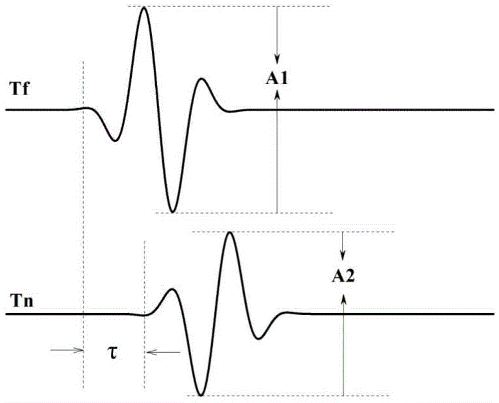
The invention discloses an acoustic logging while drilling method and device based on the double-source flyback technology. The method includes: a far transmitter and a near transmitter are used, during logging, the far transmitter Tf is stimulated first, the transmitting amplitude of the far transmitter Tf is A1, the near transmitter Tn is stimulated after a time delay tau, the transmitting polarity of Tn is opposite to that of Tf, and the transmitting amplitude of the near transmitter Tn is A2; during sound source stimulation, signals on N receivers are collected and recorded; the drill collar waves stimulated by the far transmitter and the near transmitter reach the positions of the receivers at the same time, the polarities of the drill collar waves of the far transmitter and the near transmitter are different, the amplitude of the drill collar waves of the far transmitter and the near transmitter are the same, the drill collar waves of the far transmitter and the near transmitter are overlaid and balanced off, and drill collar wave compression is achieved; a sound wave interference method is used to compress the influence of the residual drill collar waves in subsequent data processing, the speed of stratum waves is extracted, and the acoustic logging while drilling technology which needs no sound insulation devices is formed. The acoustic logging while drilling method has the advantages that the drill collar wave interference during single pole longitudinal wave logging while drilling is solved, drill strength destroying caused by grooving is avoided, and instrument machining difficulty and manufacturing cost are lowered.

Description

Technical field [0001] The invention belongs to the field of geophysical logging, and relates to an acoustic logging while drilling method and device, in particular to an acoustic logging while drilling method and device based on dual-source flyback technology. Background technique [0002] Sonic logging is an important geophysical logging method. Its main purpose is to measure the vertical and horizontal wave velocity of the formation, and then to evaluate the porosity and other reservoir parameters of the formation. Logging while drilling technology (LWD) has developed rapidly in the past ten years. Because it can complete logging operations while drilling, it greatly saves the rig time, especially in the current increasing offshore oil and gas exploration and development operations. There are very good application prospects. However, as one of the key technologies of logging while drilling, sonic logging while drilling technology is relatively lagging behind. The main reason ...

Claims


Application Information

Patent Timeline
IPC IPC(8): E21B47/00E21B49/00
CPCE21B47/00E21B49/00
Inventor 唐晓明张博苏远大
Owner CHINA UNIV OF PETROLEUM (EAST CHINA)
Learn More