A gas diffuser and aeration device

A gas disperser and gas dispersing technology, which are applied in water aeration, chemical instruments and methods, sustainable biological treatment, etc. Probability of blockage, saving energy consumption, effect of reducing pressure requirements

Active Publication Date: 2016-03-02
镇江伊博特环保科技有限公司
View PDF3 Cites 0 Cited by
  • Summary
  • Abstract
  • Description
  • Claims
  • Application Information

AI Technical Summary

Problems solved by technology

[0003] Due to the high comprehensive performance of the rubber diaphragm tubular microporous aeration device, it is currently a more commonly used aeration device. However, during the use of the rubber diaphragm tubular microporous aeration device, the inventor of the present application found that, When the rubber diaphragm type microporous aeration device stops air, only relying on the shrinkage of the rubber diaphragm cannot effectively realize the sealing of the aeration device, and a small amount of sewage will still seep into the aerator cavity, especially if the number of stop air is relatively small. The sealing effect of the rubber diaphragm is poor when there are too many or the air stop time is long; and, because the rubber diaphragm is easily damaged or aging, the probability of sewage flowing into the aerator from the damaged place is greatly increased, making the aerator The reliability of the rubber diaphragm type microporous aeration device is reduced; when the rubber diaphragm type microporous aeration device is restarted to supply air, a higher pressure is required to open the micropores of the rubber diaphragm, resulting in higher energy consumption, higher cost, and lower environmental protection performance

Method used


Image

  • A gas diffuser and aeration device
  • A gas diffuser and aeration device
  • A gas diffuser and aeration device

Examples


Embodiment 3

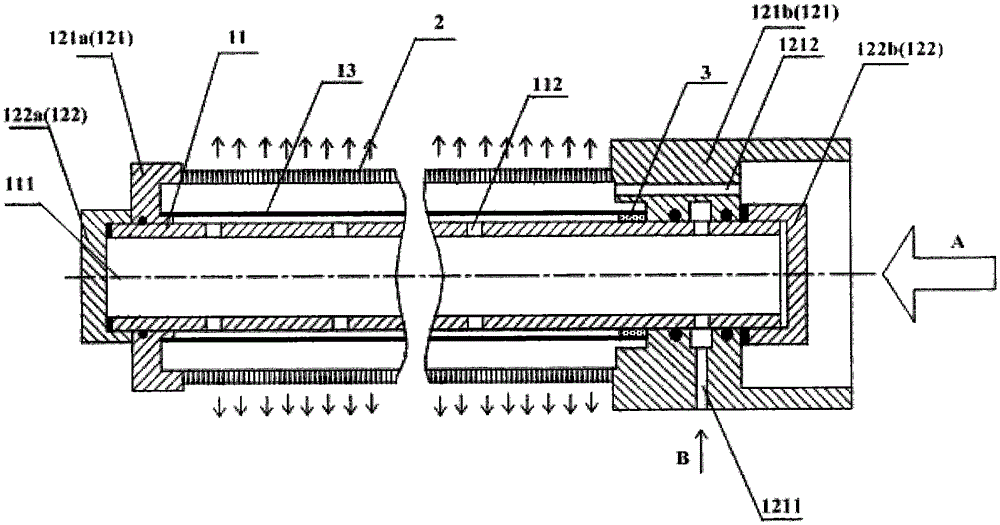
[0083] In the gas disperser provided in Embodiment 3, two caps 122 are defined as a first cap 122a and a second cap 122b. The first cap 122a and the second cap 122b respectively correspond to the openings at both ends of the support tube 11 and are fixedly connected to the two ends of the support tube 11, so that the inner space 111 of the support tube 11 forms a closed space, and the first cap 122a and the first support The seat 121a abuts against, and the second cap 122b abuts against the second support seat 121b, so as to limit the first support seat and the second support seat axially.

[0084] Such as Figure 1 ~ Figure 5b As shown, when this embodiment is installed, the first support base and the second support base usually have installation holes 1213, and the outer surface of the second support base 121b has a threaded portion 1214. The installation steps of this embodiment are as follows: Step 1, the first The cap 122a is fixedly connected to one end of the support t...


PUM

PropertyMeasurementUnit
diameteraaaaaaaaaa

Abstract

The invention relates to the technical field of sewage treatment, and discloses a gas diffuser and an aeration device. The gas diffuser comprises a strut member, an elastic sleeve which sleeves the strut member, and a gas diffusion mechanism which sleeves the elastic sleeve, wherein a space formed by the peripheral surface of the strut member and the inner surface of the elastic sleeve is communicated with a first gas pipe; and a space between the gas diffusion mechanism and the elastic sleeve is communicated with a second gas pipe. When stopping to transporting gas to the second gas pipe, high-pressure gas is injected by the first gas pipe and enters the space formed by the peripheral surface of strut member and the inner surface of the elastic sleeve to ensure that the elastic sleeve expands towards the gas diffusion mechanism until the elastic sleeve and the gas diffusion mechanism tightly fit with each other for sealing, so that the mediums in the external environment of the gas diffuser can be effectively prevented from entering the gas diffuser through a gas separation through hole of the gas diffusion mechanism so as to greatly improve the reliability of the gas diffuser.

Description

technical field [0001] The invention relates to the technical field of sewage treatment, in particular to a gas disperser and an aeration device. Background technique [0002] In the existing blast aeration system for sewage treatment, the rubber membrane microporous aeration device is currently the most commonly used aeration device, which can be divided into plate type, disc type and tube type according to the structure. The working principle of the rubber diaphragm microporous aeration device is: the fan blows the air into the aerator located at the bottom of the water through the air pipeline, and the air in the aeration device is blown through the micropores on the rubber diaphragm of the aerator. The airflow divided into small holes is dispersed into the water, forming small air bubbles and spreading upwards from the bottom of the pool, forming the stirring effect required by the process, and supplying oxygen to the bacteria in the sewage to purify the sewage; when the...

Claims


Application Information

Patent Timeline
Patent Type & Authority Patents(China)
IPC IPC(8): C02F3/02C02F7/00
CPCC02F3/02C02F7/00Y02W10/10
Inventor 李鹏飞劳森
Owner 镇江伊博特环保科技有限公司
Why Eureka
Try Eureka