Novel vertical take-up reel

A take-up reel, vertical technology, applied in the field of new vertical take-up reels, can solve the problems of inability to wind the cable, low tensile performance, inability to rewind the cable, etc. The effect of being stretched and taking up evenly

Inactive Publication Date: 2015-03-25
WUHU CHANGRUN SPECIAL COPPER
View PDF10 Cites 6 Cited by
  • Summary
  • Abstract
  • Description
  • Claims
  • Application Information

AI Technical Summary

Problems solved by technology

[0002] In the cable manufacturing industry, the take-up reel plays an important role. It can make messy cables wound together in an orderly manner, and it is convenient Unwinding; however, the previous take-up reel was short and short, and it was impossible to wind a large number of cables at one time. If a large amount of winding (horizontal direction) is performed, the cables will break away from the shackles and become messy, especially It is a copper wire that has high requirements for the weight of a single product, the elongation rate and tensile performance of the product. The special feature is that the copper wire with a large weight per unit, a large elongation rate of the product and a small tensile performance is very easy to appear in During the winding process, the copper wire is stretched or even broken; and the current take-up reels cannot take up wire reels of different sizes, and different take-up reels must be used for different sizes of reels , causing serious waste and occupying a larger production site to place

Method used


Image

  • Novel vertical take-up reel

Examples


Embodiment 1

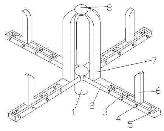
[0017] Such as figure 1 As shown, a novel vertical take-up reel includes a rotating shaft 1 and a take-up chassis 2, and the take-up chassis 2 has 3-6 pieces, which are horizontally fixed on the top of the rotating shaft 1 at equal intervals, and the take-up chassis The chassis 2 includes a limit roller 6 and a take-up roller 7, and the take-up chassis 2 is vertically fixed with a take-up roller 7 on the upper end surface of the side close to the rotating shaft 1, and the taking-up chassis 2 faces away from the rotating shaft 1 There are several grooves 3 at equal intervals on one side of the upper end surface, and a limit roller 6 matching its size and shape is vertically provided in the groove 3, passing through the groove 3 on the side of the take-up chassis 2 There is a horizontal threaded hole 5, and when the limit roller 6 is placed in the groove 3, a threaded hole is also provided horizontally at the corresponding position of the threaded hole 5, and the screw 4 passes...

Embodiment 2

[0021] The same as embodiment 1, the difference is that there are three wire receiving chassis 2, which can realize the completion of the basic wire receiving operation, and save steel materials, thereby reducing the cost.

Embodiment 3

[0023] The same as embodiment 1, the difference is that there are five wire-receiving chassis 2, which can ensure a more stable wire-receiving process.


PUM


Abstract

The invention discloses a novel vertical take-up reel, and belongs to the field of machining equipment. The novel vertical take-up reel comprises a rotating shaft and three to six take-up base plates. Each take-up base plate comprises a limiting roll and a take-up roll and is fixed to the top end of the rotating shaft, wherein the take-up roll is fixed to the upper end face of the side, close to the rotating shaft, of the take-up base plate, a plurality of grooves are formed in the upper end face of the take-up base plate, the limiting roll is arranged in one groove, horizontal threaded holes throughout the grooves are formed in the side faces of the take-up base plate, and when placed in the corresponding groove, the limiting roll is provided with a threaded hole in the part corresponding to the threaded holes and is fixed through a nut after a screw penetrates through the threaded holes. Because the limiting rolls capable of being fixed in the different grooves are arranged on the upper end faces of the take-up base plates, the distance between the take-up rolls and the limiting rolls can be adjusted, and cables of different sizes can be taken up; besides, the limiting rolls can avoid the phenomenon that when lots of cables are taken up, the cables are unconstrained and get messy in the transverse direction.

Description

technical field [0001] The invention belongs to the field of mechanical processing equipment, and more specifically relates to a novel vertical take-up reel. Background technique [0002] In the cable manufacturing industry, the take-up reel occupies an important position. It can make the messy cables be wound together in an orderly manner, and it is convenient to unwind; It is impossible to wind a large number of cables at one time. If a large amount of winding (horizontal direction) is carried out, the cables will be unbound and messy, especially for the weight of the product and the elongation and tensile properties of the product. Copper wires with higher requirements, especially copper wires with large weight per room, high product elongation and low tensile performance, are prone to be stretched or even broken during the winding process. appear; and at present, none of the existing take-up reels can take up wire reels of different sizes, and different take-up reels m...

Claims


Application Information

Patent Timeline
IPC IPC(8): B65H75/24B65H75/26
Inventor 程叙毅
Owner WUHU CHANGRUN SPECIAL COPPER
Why Eureka
Try Eureka