
Pipe fitting cold extruding forming machine and forming technology thereof

A cold extrusion and forming machine technology, applied in the field of pipe fittings processing, can solve the problems of high labor intensity of workers, increased product cost, unsightly products, etc., and achieves the effect of reducing labor intensity of workers, reducing weight, and forming beautiful shapes.

Active Publication Date: 2015-03-25
YINGKOU CHANGXIN PIPE MFG
View PDF7 Cites 0 Cited by
  • Summary
  • Abstract
  • Description
  • Claims
  • Application Information

AI Technical Summary

Problems solved by technology

Now the reducing tube is formed by heat shrinkage (thick tube becomes thinner tube), and heat shrinkage is completed by extrusion. During the extrusion process, the outer surface of the workpiece will be strained when it rubs against the mold. Grinding is required, so the existing molding technicians have high labor intensity and many processes, which increases the cost of the product, and the product is not beautiful after being polished

Method used


Image

  • Pipe fitting cold extruding forming machine and forming technology thereof
  • Pipe fitting cold extruding forming machine and forming technology thereof
  • Pipe fitting cold extruding forming machine and forming technology thereof

Examples


Embodiment 1

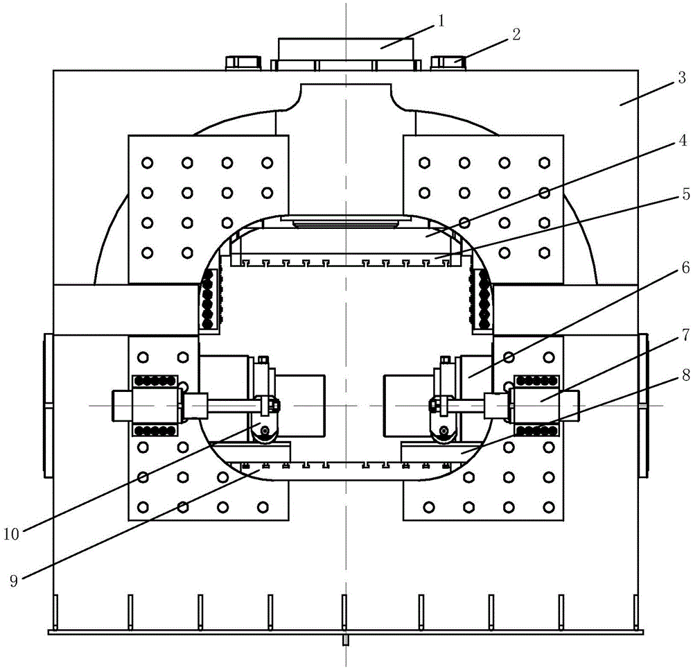
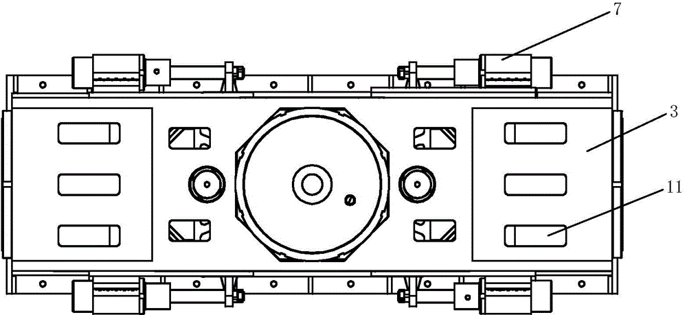
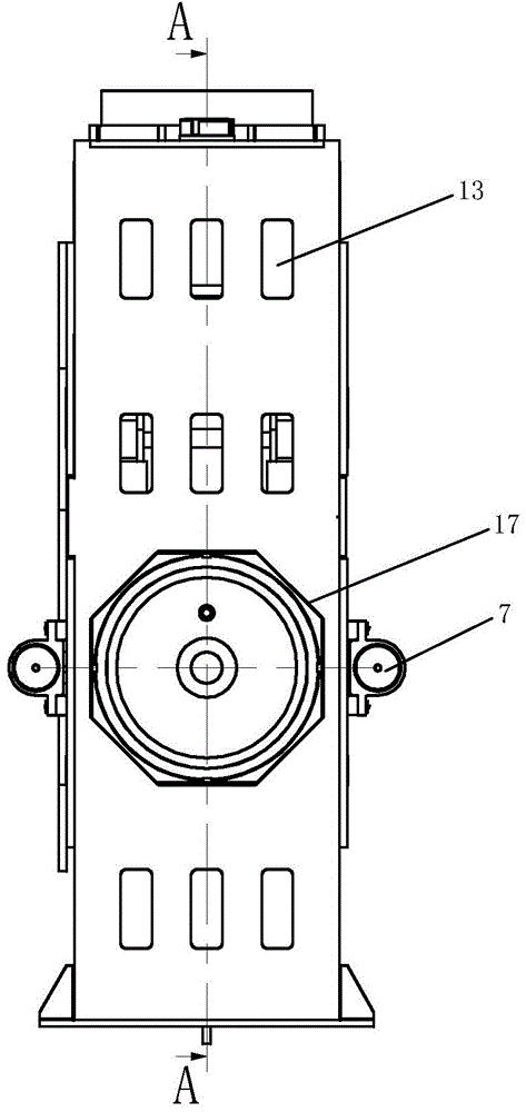
[0034] Embodiment 1: as Figure 1-Figure 4 As shown, a cold extrusion molding machine for pipe fittings of the present invention includes a frame 3 and a clamping cylinder 1 placed in the frame 3, an ejection cylinder 12, a propulsion cylinder 6, an auxiliary cylinder, and a water injection device. The middle part of the frame 3 is The working platform 13 is transparent, and the ejection cylinder 12 is set in the frame 3 below the working platform 13, and the mold clamping cylinder 1 is set in the corresponding upper frame 3, and the pushing cylinder 6, the mold clamping cylinder 1 and the pushing cylinder 1 are respectively set in the frames 3 on both sides of the working platform 13. The oil cylinders 6 are respectively provided with auxiliary oil cylinders. During work, the workpiece lower mold 9 is placed on the work platform 13, the clamping cylinder 1 is connected with the workpiece upper mold 5, and the two propulsion cylinders 6 are respectively connected with a water i...

Embodiment 2

[0055] Embodiment 2: The difference between this example and Embodiment 1 is that in this example, multiple molds are placed on the working platform 13 in the frame 3 at the same time, and a clamping cylinder 1 and two first auxiliary cylinders 2 are set, corresponding to each workpiece Two propulsion oil cylinders 6 and four second auxiliary oil cylinders 7 are set and extruded at the same time. Improve work efficiency.


PUM


Abstract

The invention belongs to the technical field of pipe fitting processing, and relates to a pipe fitting cold extruding forming machine and a forming technology of the pipe fitting cold extruding forming machine. The forming machine comprises a frame, a mold locking oil cylinder, an ejection oil cylinder, pushing oil cylinders and auxiliary oil cylinders, and the mold locking oil cylinder, the ejection oil cylinder, the pushing oil cylinders and the auxiliary oil cylinders are arranged in the frame. A through work platform is arranged in the middle of the frame, the ejection oil cylinder is arranged at the position, below the work platform, in the frame, the mold locking oil cylinder is arranged at the position, corresponding to the position above the work platform, in the frame, the pushing oil cylinders are arranged at the positions, on the two sides of the work platform, in the frame respectively, and the auxiliary oil cylinders are arranged on the mold locking oil cylinder and the pushing oil cylinders respectively. In the work process, a lower workpiece mold is placed on the work platform, the mold locking oil cylinder is connected with an upper workpiece mold, the two pushing oil cylinders are connected with water injection devices respectively, the water injection devices are connected with a workpiece in the pushing process, and sealing contact is achieved. A three-way reducing pipe is formed based on the cold extruding technology, operation and forming are easy, environmental protection and high efficiency are achieved, safety is high, and the labor intensity of workers is lowered.

Description

technical field [0001] The invention belongs to the technical field of pipe fitting processing, in particular to a cold extrusion molding machine for pipe fittings and a molding process thereof. Background technique [0002] Existing pipe fittings are generally formed by hot pressing molding equipment, and the required special-shaped pipe fittings are obtained through high-temperature hot-melt deformation. A large amount of fuel is wasted in the heating process. Coke ovens are generally used for heating, which not only causes environmental pollution, but also the working environment for workers is poor and dangerous. High, prone to accidents. In addition, as far as the diameter of the reducer is too large, it needs multiple cycles of heating and deformation before it can be formed, because multiple heating will cause iron oxide to form on the surface of the workpiece and fall off, and the surface of the workpiece has unevenness and needs to be polished. Now the reducin...

Claims


Application Information

Patent Timeline
IPC IPC(8): B21C23/08B21C25/02
Inventor 刘国祥刘旭东
Owner YINGKOU CHANGXIN PIPE MFG
Learn More