
Finger mechanism of anthropomorphic myoelectrical artificial hand

A myoelectric and prosthetic hand technology, which is applied in prosthetics, medical science, etc., can solve the problems of not being able to grasp multiple gestures, not being able to realize the relative movement of fingers and knuckles, and limiting the application range of prosthetic hands, etc., to achieve simple structure and appropriate Safe and reliable operation function and structure

Active Publication Date: 2015-03-25
SOUTH CHINA UNIV OF TECH
View PDF8 Cites 5 Cited by
  • Summary
  • Abstract
  • Description
  • Claims
  • Application Information

AI Technical Summary

Problems solved by technology

Most of the prosthetic hands currently used clinically only have a single degree of freedom
In the single-degree-of-freedom movement of the prosthetic hand, each finger is rigid, and there is no knuckle that can move independently. In addition to the opening and closing movement of the fingers relative to the palm, the relative movement between the knuckles of the fingers cannot be realized.
The rigid finger mechanism ensures that the finger mechanism of the prosthetic hand is simple in structure and reliable in use, but it cannot realize the grasping ability of various gestures, thus limiting the application range of the prosthetic hand
[0005] At present, researchers have done a lot of research on prosthetic hands, but in fact most of the prosthetic hands are still in the experimental stage, and there is still a big gap from commercialization and practicality.

Method used


Image

  • Finger mechanism of anthropomorphic myoelectrical artificial hand
  • Finger mechanism of anthropomorphic myoelectrical artificial hand
  • Finger mechanism of anthropomorphic myoelectrical artificial hand

Examples


Embodiment Construction

[0040] The purpose of the present invention will be further described in detail below in conjunction with the accompanying drawings and specific embodiments, and the embodiments cannot be repeated here one by one, but the implementation of the present invention is not therefore limited to the following embodiments.

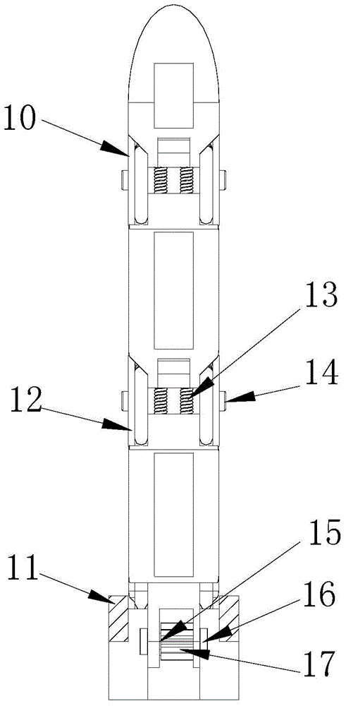
[0041] Such as Figures 1 to 3 As shown, a finger mechanism of a humanoid myoelectric prosthetic hand includes base 1, proximal phalanx 3, middle phalanx 6 and distal phalanx 9 from bottom to top, and also includes metacarpal joint 2, proximal phalanx joint 5, Distal phalangeal joint 8, proximal driving tendon 4 and distal driving tendon 7, the base 1 and proximal phalanx 3 are rotationally connected through metacarpal joint 2, and the proximal phalanx 3 and middle phalanx 6 are rotationally connected through proximal phalanx joint 5, The middle phalanx 6 and the distal phalanx 9 are rotationally connected through the distal phalanx joint 8; the proximal driving t...


PUM


Abstract

The invention discloses a finger mechanism of an anthropomorphic myoelectrical artificial hand. The finger mechanism sequentially comprises a base, a near knuckle, a middle knuckle and a far knuckle from bottom to top and further comprises a metacarpal bone joint, a near phalanx joint, a far phalanx joint, a near driving tendon and a far driving tendon, wherein the base is in rotary connection with the near knuckle through the metacarpal bone joint, the near knuckle is in rotary connection with the middle knuckle through the near phalanx joint, and the middle knuckle is in rotary connection with the far knuckle through the far phalanx joint. The near driving tendon is connected between the near phalanx joint and the metacarpal bone joint, the far knuckle is connected between the far phalanx joint and the near phalanx joint, and the near phalanx joint and the far phalanx joint are of spring type flexible hinge structures. The finger mechanism can achieve finger bending and stretching only by needing a driving unit, adopts tendon drive to achieve coupling motions of the joints, enables a finger structure to be simple, safe and reliable by applying spring type flexible hinges, is flexible in motion and has an appropriate operating function.

Description

technical field [0001] The invention relates to the technical field of hand prosthetics, in particular to a prosthetic finger mechanism based on flexible hinge design and myoelectric signal principle design. Background technique [0002] Myoelectric prosthetic hand is an anthropomorphic prosthetic hand controlled by human muscle electric signal, which has beautiful appearance and perfect function. The EMG signal is derived from the electrical signal generated when the user's muscles voluntarily contract. This prosthetic hand uses electrical signals collected by electrodes installed on the surface of the remaining arm muscles to control the motors, thereby driving the movement of the prosthetic hand. [0003] The compliant mechanism is a new type of mechanism that uses the elastic deformation of the component itself to complete the transmission and conversion of movement and force. Compliant mechanisms mainly rely on the deformation of the compliant components in the mechan...

Claims


Application Information

Patent Timeline
Patent Type & Authority Applications(China)
IPC IPC(8): A61F2/56A61F2/72
Inventor 王念峰劳锟沂张宪民
Owner SOUTH CHINA UNIV OF TECH
Learn More