Magnetic resonance imaging device and magnetic resonance imaging method
A magnetic resonance imaging and nuclear magnetic resonance technology, applied in medical science, diagnosis, diagnostic recording/measurement, etc., can solve the problem of low versatility and achieve the effect of preventing the extension of imaging time
- Summary
- Abstract
- Description
- Claims
- Application Information
AI Technical Summary
Problems solved by technology
Method used
Image

Examples
no. 1 approach
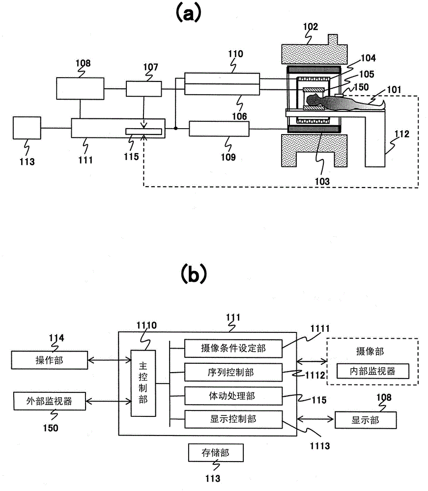
[0041] The MRI apparatus of the present embodiment is characterized in that the MRI apparatus uses a respiratory movement monitor (one form of an internal monitor) using navigator echoes, and a respiratory movement monitor of the abdominal wall (one form of an external monitor) such as a pressure sensor. ), to serve as multiple motion monitors.
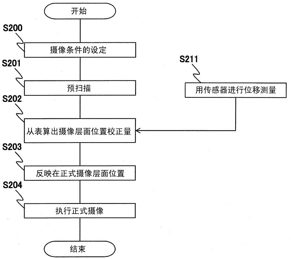
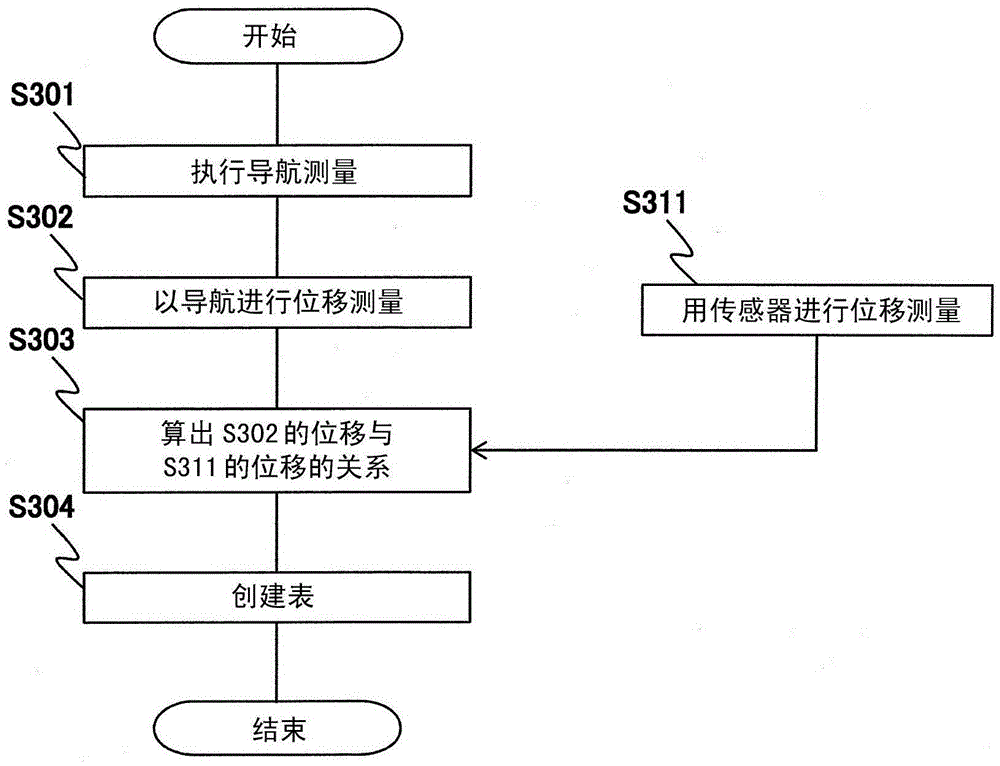
[0042] exist figure 2 as well as image 3 The procedure of imaging control performed by the control unit 111 is shown. figure 2 It is a flowchart showing the procedure of the whole imaging, image 3 is a flowchart showing a part of prescanning.
[0043] First, the imaging conditions are set in the imaging condition setting unit 1111 (S200). Here, the slice position is set based on the scout scan (a large-area image captured on the subject with a lower resolution before the examination). (direction), slice width, gate window and other conditions related to the imaging area, and set the parameters of the pulse sequence used in the...
no. 2 approach
[0070] This embodiment is the same as the first embodiment in that position information from an external monitor such as a pressure sensor is associated with position information from a navigation sequence, and imaging is controlled using the associated information during main imaging. The present embodiment is characterized in that it includes an update function for establishing related information. That is, the MRI apparatus of the present embodiment includes a storage unit that stores associated information created by a body motion processing unit, and the body motion processing unit uses newly acquired body motion information from at least one of a plurality of body motion monitors to update the stored Association information in the storage unit.
[0071] exist Figure 9 The procedure of the second embodiment is shown. exist Figure 9 in, with figure 2 Steps with the same processing content as the steps in are denoted by the same reference numerals. First, in the cas...
no. 3 approach
[0080] In the first embodiment, the case of estimating the position of the direction measured in the navigation sequence from the body movement correlation information, and performing slice correction or gating on the estimated direction in the main imaging is described, but the characteristic of this embodiment is This is to perform slice correction in two or more directions using both the estimated position and the position actually measured by the external monitor. That is, in the MRI apparatus according to this embodiment, the plurality of body motion monitors include body motion monitors that detect body motion information in different directions of motion, and the control unit controls the imaging unit using the body motion information in different directions.
[0081] The sequence of this embodiment is the same as figure 2 The sequence shown for the first embodiment is substantially the same. However, in this embodiment, the step S202 of calculating the correction amo...
PUM
 Abstract
Description
Claims
Application Information
 - R&D
- Intellectual Property
- Life Sciences
- Materials
- Tech Scout
- Unparalleled Data Quality
- Higher Quality Content
- 60% Fewer Hallucinations
Browse by: Latest US Patents, China's latest patents, Technical Efficacy Thesaurus, Application Domain, Technology Topic, Popular Technical Reports.
© 2025 PatSnap. All rights reserved.Legal|Privacy policy|Modern Slavery Act Transparency Statement|Sitemap|About US| Contact US: help@patsnap.com