
Bilateral numerical control electroslag welding device

A technology of electroslag welding and welding torch, which is applied in the field of double-sided numerical control electroslag welding, which can solve the problems of poor support stability of welding torch, difficult welding work, and difficult to guarantee welding quality, etc., and achieves improved processing safety, convenient operation, and simple structure Effect

Inactive Publication Date: 2015-03-18
TIANJIN JINPU STEEL STRUCTURE
View PDF0 Cites 9 Cited by
  • Summary
  • Abstract
  • Description
  • Claims
  • Application Information

AI Technical Summary

Problems solved by technology

[0002] In the field of steel structure production, especially in the production of H-shaped profiles and I-beams, due to the large volume and weight of the workpiece, welding is usually carried out by fixing the workpiece and moving the welding machine. This method has high requirements for the adjustment of the welding machine itself. , very long-distance movement and small-scale precise adjustment are required. Most of the existing welding is long-distance movement adjustment, which is difficult to adjust and takes a long time. Moreover, the stability of the welding torch support is poor, and even affects the welding process during the movement. The transportation of welding wire is prone to failure, which makes the welding work difficult, the labor intensity of workers is high, and the production efficiency is low, and the welding quality is difficult to guarantee

Method used


Image

  • Bilateral numerical control electroslag welding device

Examples


Embodiment Construction

[0013] The present invention will be further described in detail below in conjunction with the accompanying drawings and through specific embodiments. The following embodiments are only descriptive, not restrictive, and cannot limit the protection scope of the present invention.

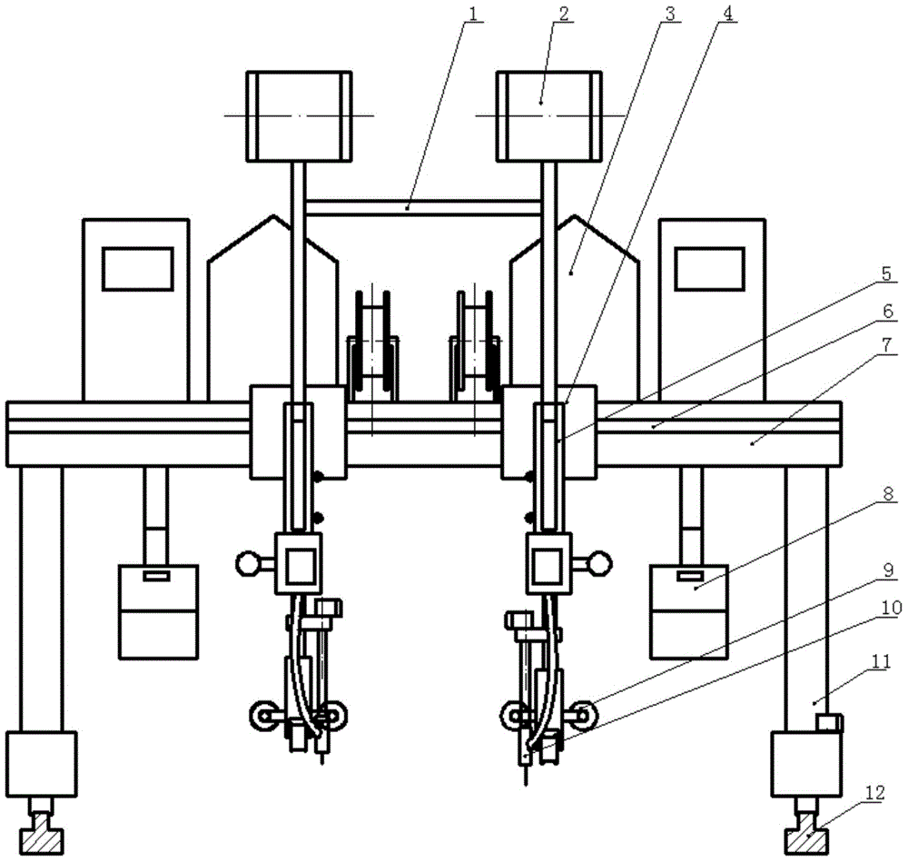
[0014] A kind of double-sided numerical control electroslag welding, on the guide rail 12 that is arranged in parallel, horizontally guides and installs the door frame 11, and the door frame is driven by a walking motor (not marked in the figure), and the beam 7 on the front side wall of the door frame A transverse slide frame 6 is installed horizontally, on which two horizontal sliding welding arms 4 are installed symmetrically, and a welding torch 10 is installed at the lower end of the welding arm; a numerical control adjustment panel 8 is respectively installed on both sides of the lower end of the gantry beam .

[0015] The innovation point of the present invention is:

[0016] There is a quadr...


PUM


Abstract

The invention relates to a bilateral numerical control electroslag welding device. A wire feeding frame which is of a quadrangle frame structure is fixedly arranged at the middle part of the upper end of a portal; wire feeding controllers are fixedly arranged at the upper ends of both sides of the wire feeding frame; the wire feeding speed is controlled by the wire feeding controllers by virtue of an electric cabinet; welding wire bins are fixedly arranged at an interval at the middle part of the upper end of the portal behind the wire feeding frame; the lower parts of welding arms are provided with telescopic sleeves in a coaxial regulating manner; the telescopic sleeves regulate welding guns to move up and down; steering devices are arranged at the lower parts of the telescopic sleeves; the welding guns are fixedly arranged on the steering devices. The bilateral numerical control electroslag welding device has a simple structure, is scientifically designed, is convenient to operate, has high welding accuracy, is convenient and reliable to operate, is convenient to regulate and is accurate to position; production efficiency can be effectively promoted; welding quality is ensured.

Description

technical field [0001] The invention relates to the field of steel structure production, especially a kind of double-sided numerical control electroslag welding. Background technique [0002] In the field of steel structure production, especially in the production of H-shaped profiles and I-beams, due to the large volume and weight of the workpiece, welding is usually carried out by fixing the workpiece and moving the welding machine. This method has high requirements for the adjustment of the welding machine itself. , very long-distance movement and small-scale precise adjustment are required. Most of the existing welding is long-distance movement adjustment, which is difficult to adjust and takes a long time. Moreover, the stability of the welding torch support is poor, and even affects the welding process during the movement. The transportation of welding wire is prone to failure, which makes the welding work difficult, the labor intensity of workers is high, and the prod...

Claims


Application Information

Patent Timeline
Patent Type & Authority Applications(China)
IPC IPC(8): B23K25/00B23K37/02
CPCB23K25/00
Inventor 陈洪利
Owner TIANJIN JINPU STEEL STRUCTURE
Learn More