Hydraulic driven punching machining device
A processing device and hydraulic device technology, applied in the direction of perforating tools, metal processing equipment, manufacturing tools, etc., can solve the problems of complex overall structure and easy jamming during operation, and achieve broad market prospects, simple structure, and convenient use. Effect
- Summary
- Abstract
- Description
- Claims
- Application Information
AI Technical Summary
Problems solved by technology
Method used
Image

Examples
Embodiment 1
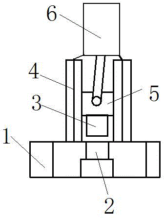
[0014] This embodiment provides a hydraulically driven punching processing device, which is characterized in that: the hydraulically driven punching processing device includes a hydraulically driven punching processing device base 1, a punching female die 2, and a punching male die 3. Male mold slideway 4, connecting slider 5, hydraulic device 6;
[0015] Wherein: the punching die 2 is located in the base 1 of the hydraulically driven punching processing device, the male die slideway 4 is vertically installed on the hydraulically driven punching processing device base 1, and the connecting slider 5 is installed in the male die slideway 4 , The punching male die 3 is installed below the connecting slider 5, and the hydraulic device 6 is connected with the connecting slider 5 through a connecting rod.
[0016] The edge of the punching male die 3 and the punching female die 2 has a cutting edge.
[0017] There is a guide groove between the punching male die 3) and the male die s...
Embodiment 2
[0019] This embodiment provides a hydraulically driven punching processing device, which is characterized in that: the hydraulically driven punching processing device includes a hydraulically driven punching processing device base 1, a punching female die 2, and a punching male die 3. Male mold slideway 4, connecting slider 5, hydraulic device 6;
[0020] Wherein: the punching die 2 is located in the base 1 of the hydraulically driven punching processing device, the male die slideway 4 is vertically installed on the hydraulically driven punching processing device base 1, and the connecting slider 5 is installed in the male die slideway 4 , The punching male die 3 is installed below the connecting slider 5, and the hydraulic device 6 is connected with the connecting slider 5 through a connecting rod.
[0021] The edge of the punching male die 3 and the punching female die 2 has a cutting edge.
Embodiment 3
[0023] This embodiment provides a hydraulically driven punching processing device, which is characterized in that: the hydraulically driven punching processing device includes a hydraulically driven punching processing device base 1, a punching female die 2, and a punching male die 3. Male mold slideway 4, connecting slider 5, hydraulic device 6;
[0024] Wherein: the punching die 2 is located in the base 1 of the hydraulically driven punching processing device, the male die slideway 4 is vertically installed on the hydraulically driven punching processing device base 1, and the connecting slider 5 is installed in the male die slideway 4 , The punching male die 3 is installed below the connecting slider 5, and the hydraulic device 6 is connected with the connecting slider 5 through a connecting rod.
PUM
 Abstract
Description
Claims
Application Information
 - R&D
- Intellectual Property
- Life Sciences
- Materials
- Tech Scout
- Unparalleled Data Quality
- Higher Quality Content
- 60% Fewer Hallucinations
Browse by: Latest US Patents, China's latest patents, Technical Efficacy Thesaurus, Application Domain, Technology Topic, Popular Technical Reports.
© 2025 PatSnap. All rights reserved.Legal|Privacy policy|Modern Slavery Act Transparency Statement|Sitemap|About US| Contact US: help@patsnap.com