Logic protection amplification type blue-light LED lamp protecting system

A logic protection, LED lamp technology, applied in the direction of light source, electric light source, electric lamp circuit layout, etc., can solve the problems of high energy consumption, complex structure, poor comprehensive protection, etc., to improve sensitivity and accuracy, overcome delay effect, power low consumption effect

Inactive Publication Date: 2015-03-11
CHENGDU COPOO TECH
View PDF0 Cites 2 Cited by
  • Summary
  • Abstract
  • Description
  • Claims
  • Application Information

AI Technical Summary

Problems solved by technology

[0004] The purpose of the present invention is to overcome the defects of complex structure, high energy consumption, and poor comprehensive protection in the current LED lamp protection system, and provide a logic protection amplified blue LED lamp protection system

Method used


Image

  • Logic protection amplification type blue-light LED lamp protecting system
  • Logic protection amplification type blue-light LED lamp protecting system
  • Logic protection amplification type blue-light LED lamp protecting system

Examples


Embodiment

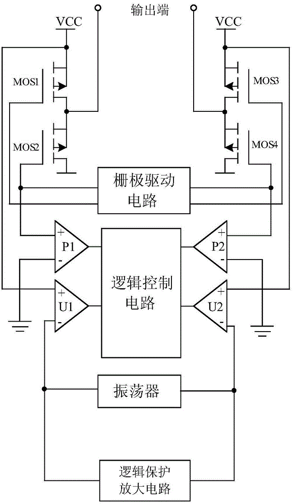
[0025] like figure 1 As shown, the blue LED lamp protection system of the present invention is mainly composed of a gate drive circuit, a logic control circuit, an oscillator, a power amplifier P1, a power amplifier P2, a pulse comparator U1, a pulse comparator U2, a field effect transistor MOS1, It consists of field effect transistor MOS2, field effect transistor MOS3 and field effect transistor MOS4, and a logic protection amplifier circuit connected in series between the pulse comparator U1 and the pulse comparator U2.

[0026] When connected, the output terminals of the power amplifier P1, the output terminals of the power amplifier P2, the output terminals of the pulse comparator U1 and the output terminals of the pulse comparator U2 are all connected to the logic control circuit, and the two output terminals of the oscillator are respectively It is connected with the negative input terminal of the pulse comparator U1 and the negative input terminal of the pulse comparato...


PUM


Abstract

The invention discloses a logic protection amplification type blue-light LED lamp protecting system. The logic protection amplification type blue-light LED lamp protecting system mainly comprises a grid drive circuit, a logic control circuit, a power amplifier P1, a power amplifier P2, a pulse comparator U1, a pulse comparator U2, a field-effect transistor MOS1, a field-effect transistor MOS2, a field-effect transistor MOS3, a field-effect transistor MOS4 and an oscillator. The power amplifiers P1 and P2 and the pulse comparators U1 and U2 are connected with the logic control circuit; grids of the field-effect transistors MOS1, MOS2, MOS3 and MOS4 are connected with the grid drive circuit; the oscillator is connected in series between the cathode input end of the pulse comparator U1 and the cathode input end of the pulse comparator U2. The logic protection amplification type blue-light LED lamp protecting system is characterized in that a logic protection amplification circuit is also connected in series between the cathode input end of the pulse comparator U1 and the cathode input end of the pulse comparator U2. The logic protection amplification type blue-light LED lamp protecting system has functions of short-circuit protection, overvoltage protection and open circuit protection and has low power consumption which is one third of power consumption of a conventional protection circuit.

Description

technical field [0001] The invention relates to an LED protection circuit, in particular to a logic protection amplified blue LED lamp protection system. Background technique [0002] At present, due to the characteristics of low energy consumption, long service life, safety and environmental protection, LED lamps have become one of the mainstream products for people's living lighting. Since LED lamps are different from traditional incandescent lamps, they need to be driven by a dedicated drive circuit, so there are various protection systems on the market to prevent the drive system from being interfered by internal or external adverse factors. [0003] Although most of these protection systems have short-circuit protection functions and overheat protection functions, the structures of these protection systems are often relatively complicated, and their maintenance is relatively difficult. At the same time, the energy consumption of these protection systems is relatively h...

Claims


Application Information

Patent Timeline
Patent Type & Authority Applications(China)
IPC IPC(8): H05B37/02
CPCY02B20/40
Inventor 罗娅车容俊
Owner CHENGDU COPOO TECH
Why Eureka
Try Eureka