
Calibration plate and a thermal infrared camera calibration method based on same

A calibration method and a calibration board technology, applied in image data processing, instruments, calculations, etc., can solve problems such as complex calibration procedures, lack of detailed information in images, and low resolution of thermal infrared cameras, and achieve simple calibration methods and structural Simple, easy-to-make effects

Inactive Publication Date: 2015-03-11
CMA METEOROLOGICAL OBSERVATION CENT
View PDF3 Cites 20 Cited by
  • Summary
  • Abstract
  • Description
  • Claims
  • Application Information

AI Technical Summary

Problems solved by technology

[0002] At present, camera self-calibration technology and theoretical research are mainly concentrated in the visible light band. Due to the low resolution of the thermal infrared camera and the lack of detailed information in the image, the existing calibration method cannot obtain good calibration accuracy. The infrared camera receives the target image. Thermal infrared radiation makes it impossible to use traditional calibration boards for calibration; while the existing infrared camera calibration targets mainly use round steel balls and high-precision 3D attitude instruments, which are expensive, and require auxiliary heat sources during calibration, and the calibration procedures are more complicated

Method used


Image

  • Calibration plate and a thermal infrared camera calibration method based on same
  • Calibration plate and a thermal infrared camera calibration method based on same

Examples


Embodiment Construction

[0020] Below, the substantive features and advantages of the present invention will be further described in conjunction with examples, but the present invention is not limited to the listed examples.

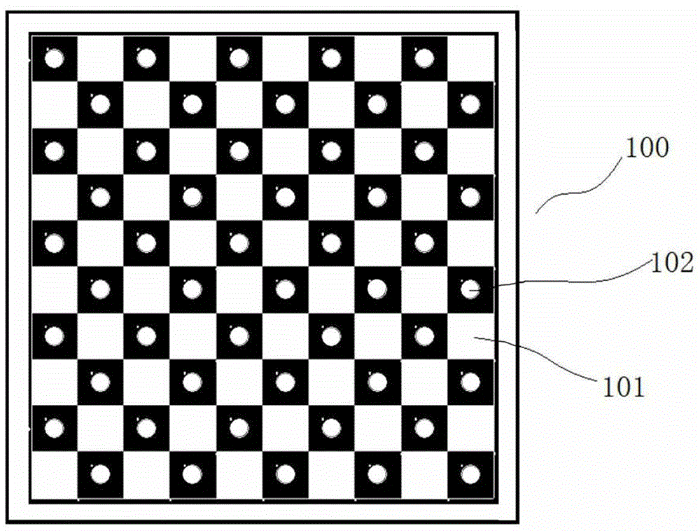
[0021] See figure 1 ,Should figure 1 The structure of the calibration board of the present invention is shown, the calibration board includes a square substrate 100, the substrate is provided with a checkerboard layer 101 for calibration of a visible light machine camera, and the checkerboard layer is located in front of the substrate On the surface, the checkerboard layer is a chessboard pattern layer formed by an array of black and white squares with the same size; wherein, a circular heating chip 102 for infrared camera calibration is installed on the front surface of each black square, The temperature of the circular heating sheet is controllable and connected to a temperature-controllable heating circuit; the center of the circular heating sheet coincides with the center o...


PUM


Abstract

The invention relates to a calibration plate and a thermal infrared camera calibration method based on the same. The calibration plate comprises a square substrate, wherein a checkerboard layer for visible light camera calibration is arranged on the substrate; the checkerboard layer is positioned on the front surface of the substrate; the checkerboard layer is an international chessboard pattern layer formed by black and white square arrays with the same size; a temperature-controllable circular heating piece for thermal infrared camera calibration is mounted on the front surface of each black square; the circular heating piece is connected with a heating circuit; the circular center of the circular heating piece is superposed with the center of the black square; the circular heating piece is positioned within the boundary of each black square. When the calibration plate is adopted for the thermal infrared camera calibration, the calibration method is simple and accurate; the calibration plate is convenient to manufacture, low in cost and convenient to popularize; the calibration plate and the thermal infrared camera calibration method based on the calibration plate can be directly applied to the field of calibration of infrared imaging instruments for weather study, aviation and surveying and mapping and the like.

Description

technical field [0001] The invention belongs to the technical field of camera calibration, and in particular relates to a calibration board and a thermal infrared camera calibration method based on the calibration board. Background technique [0002] At present, camera self-calibration technology and theoretical research are mainly concentrated in the visible light band. Due to the low resolution of the thermal infrared camera and the lack of detailed information in the image, the existing calibration method cannot obtain good calibration accuracy. The infrared camera receives the target image. Thermal infrared radiation cannot be calibrated with traditional calibration boards; while the existing infrared camera calibration targets mainly use circular steel balls and high-precision 3D attitude instruments, which are expensive, and require auxiliary heat sources during calibration, and the calibration procedure is complicated. Contents of the invention [0003] The object o...

Claims


Application Information

Patent Timeline
IPC IPC(8): G06T7/00
CPCG06T7/80
Inventor 陶法马舒庆秦勇
Owner CMA METEOROLOGICAL OBSERVATION CENT
Learn More