Fork-limited two-stage speed change main reducer assembly

A main reducer and assembly technology, applied in the field of tricycle reducer

Inactive Publication Date: 2015-03-11
CHONGQING XIANYOU TECH DEV
View PDF6 Cites 5 Cited by
  • Summary
  • Abstract
  • Description
  • Claims
  • Application Information

AI Technical Summary

Problems solved by technology

but requires a separate transmission to shift it

Method used


Image

  • Fork-limited two-stage speed change main reducer assembly
  • Fork-limited two-stage speed change main reducer assembly
  • Fork-limited two-stage speed change main reducer assembly

Examples


Embodiment Construction

[0038] Embodiments of the present invention are described below through specific examples, and those skilled in the art can easily understand other advantages and effects of the present invention from the content disclosed in this specification. The present invention can also be implemented or applied through other different specific implementation modes, and various modifications or changes can be made to the details in this specification based on different viewpoints and applications without departing from the spirit of the present invention.

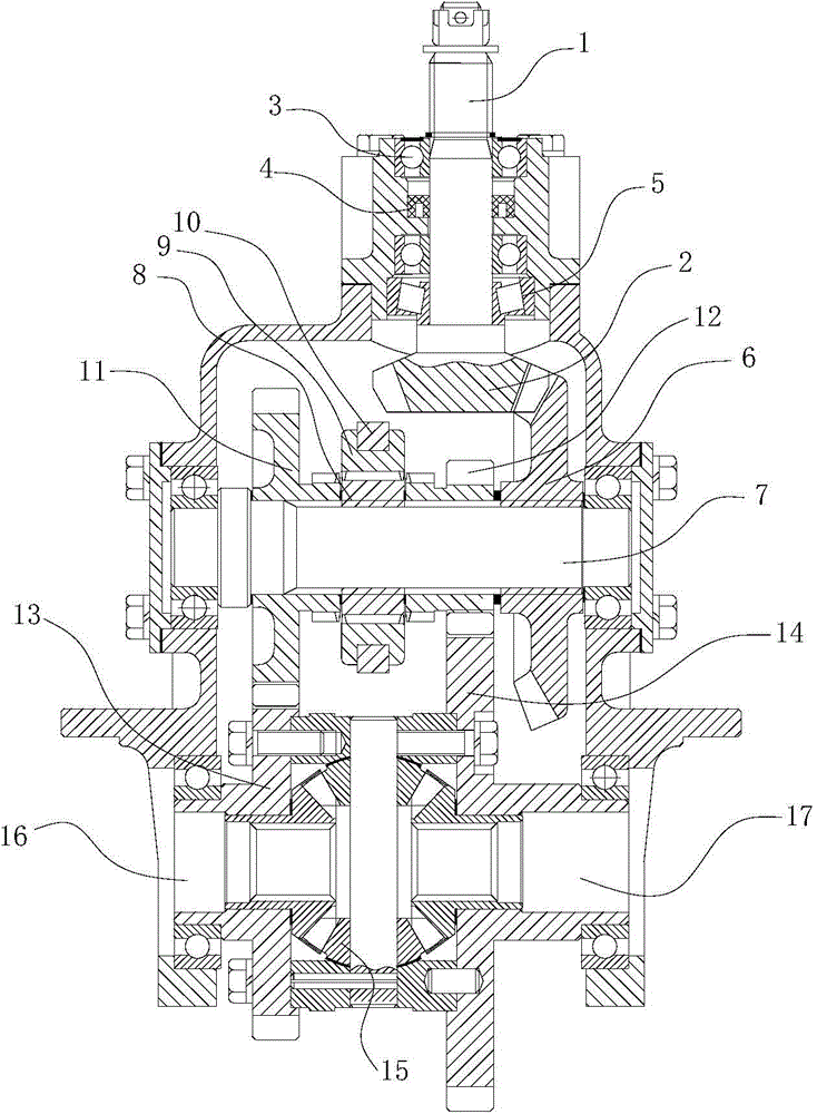
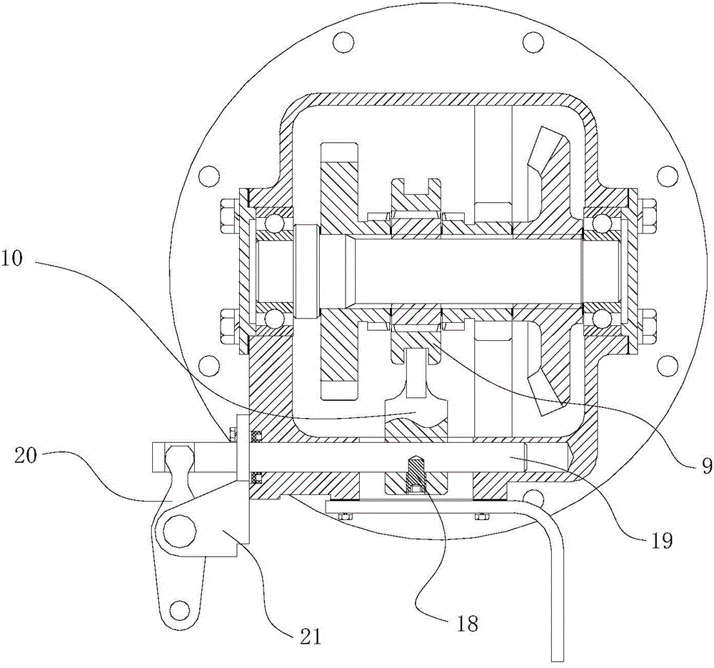
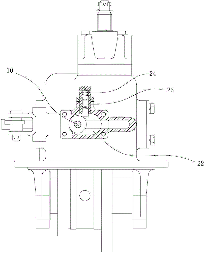
[0039] According to the manual attached figure 1 The two-stage variable speed main reducer assembly with the shift fork limit shown includes the input shaft 1, which extends through the box body to the inner side of the box body and is provided with a bevel gear 2, and the input shaft 1 and the box body pass through Two sets of deep groove ball bearings 3 cooperate with the oil seal 4, and a set of tapered roller bearings 5 ​​are arra...


PUM


Abstract

The invention provides a fork-limited two-stage speed change main reducer assembly. The assembly comprises an input shaft, wherein the inner end, penetrating through a box body, of the input shaft is provided with a bevel gear; the bevel gear is engaged with a main driven gear; the main driven gear is fixedly arranged on a driven shaft; the driven shaft is also fixedly provided with a gear hub and a gear sleeve; the gear sleeve can move left and right through driving of a fork; the tail end of the fork pulls the gear sleeve to move; the other end of the fork is fixed to a fork shaft through a pin; the fork shaft penetrates through the box body; the tail end of the fork shaft is hinged to a shift arm; the middle position of the shift arm is hinged to a shift arm bracket; the fork is arranged in a fork hole; the fork hole is an elliptical hole; the side edge of the fork hole is provided with a positioning hole; a positioning pin is arranged in the positioning hole; the root part of the positioning pin is provided with a spring. The shift arm is pulled to rotate around the hinge point of the bracket, and the fork shaft is driven to move left and right, and the gear sleeve is pulled to move.

Description

technical field [0001] The invention relates to a speed reducer for a tricycle, in particular to a speed reducer for a tricycle with a shifting function. Background technique [0002] The reducer plays the role of matching the speed and transmitting torque between the prime mover and the working machine or the actuator. The reducer is a relatively precise machine, and its purpose is to reduce the speed. The reducer is generally used for low-speed and high-torque transmission equipment. The motor, internal combustion engine or other high-speed running power is used to achieve the purpose of deceleration through the gear with a small number of teeth on the input shaft of the reducer and the large gear on the output shaft. Ordinary The reducer will also have several pairs of gears with the same principle to achieve the ideal deceleration effect. The ratio of the number of teeth of the large and small gears is the transmission ratio. [0003] In a tricycle, the reducer needs to...

Claims


Application Information

Patent Timeline
IPC IPC(8): F16H1/14F16H63/32F16H57/023
CPCF16H1/14F16H57/023F16H63/32
Inventor 金少华李政庭毛学兵
Owner CHONGQING XIANYOU TECH DEV
Why Eureka
Try Eureka