
Construction method of aluminium alloy material end milling-cutting force and cutting processing deformation model

An aluminum alloy material, end milling cutting technology, applied in special data processing applications, instruments, electrical digital data processing and other directions, can solve problems such as not suitable for cutting theory

Active Publication Date: 2015-03-04
BEIJING INSTITUTE OF TECHNOLOGYGY
View PDF4 Cites 34 Cited by
  • Summary
  • Abstract
  • Description
  • Claims
  • Application Information

AI Technical Summary

Problems solved by technology

[0002] At present, the research on the casting process of cast aluminum alloy materials at home and abroad has been relatively mature, but the research on the mechanical properties of different cast aluminum alloy materials is still limited to the study of static mechanical properties. The research on the dynamic mechanical properties of cast aluminum alloy materials has not yet been carried out. Therefore, it is of great significance to study the dynamic mechanical properties of cast aluminum alloy materials under high-speed cutting conditions for the study of machining deformation mechanism.
[0003] According to the characteristics of cast aluminum alloy materials, the main processing method of cast aluminum alloy complex box parts is end milling. When large-scale plane processing is performed, it is affected by the diameter of the end mill tool, although a higher spindle speed is not selected for processing. , the selection of large-diameter end milling tools can still achieve a high cutting speed (>1000m / min) during the cutting process, so it is not suitable for analysis with traditional cutting theory, and it is necessary to establish a research method suitable for high-speed end milling

Method used


Image

  • Construction method of aluminium alloy material end milling-cutting force and cutting processing deformation model
  • Construction method of aluminium alloy material end milling-cutting force and cutting processing deformation model
  • Construction method of aluminium alloy material end milling-cutting force and cutting processing deformation model

Examples


Embodiment Construction

[0082] In order to make the object, technical solution and advantages of the present invention clearer, the present invention will be further described in detail below in conjunction with the accompanying drawings and embodiments. It should be understood that the specific embodiments described here are only used to explain the present invention, not to limit the present invention.

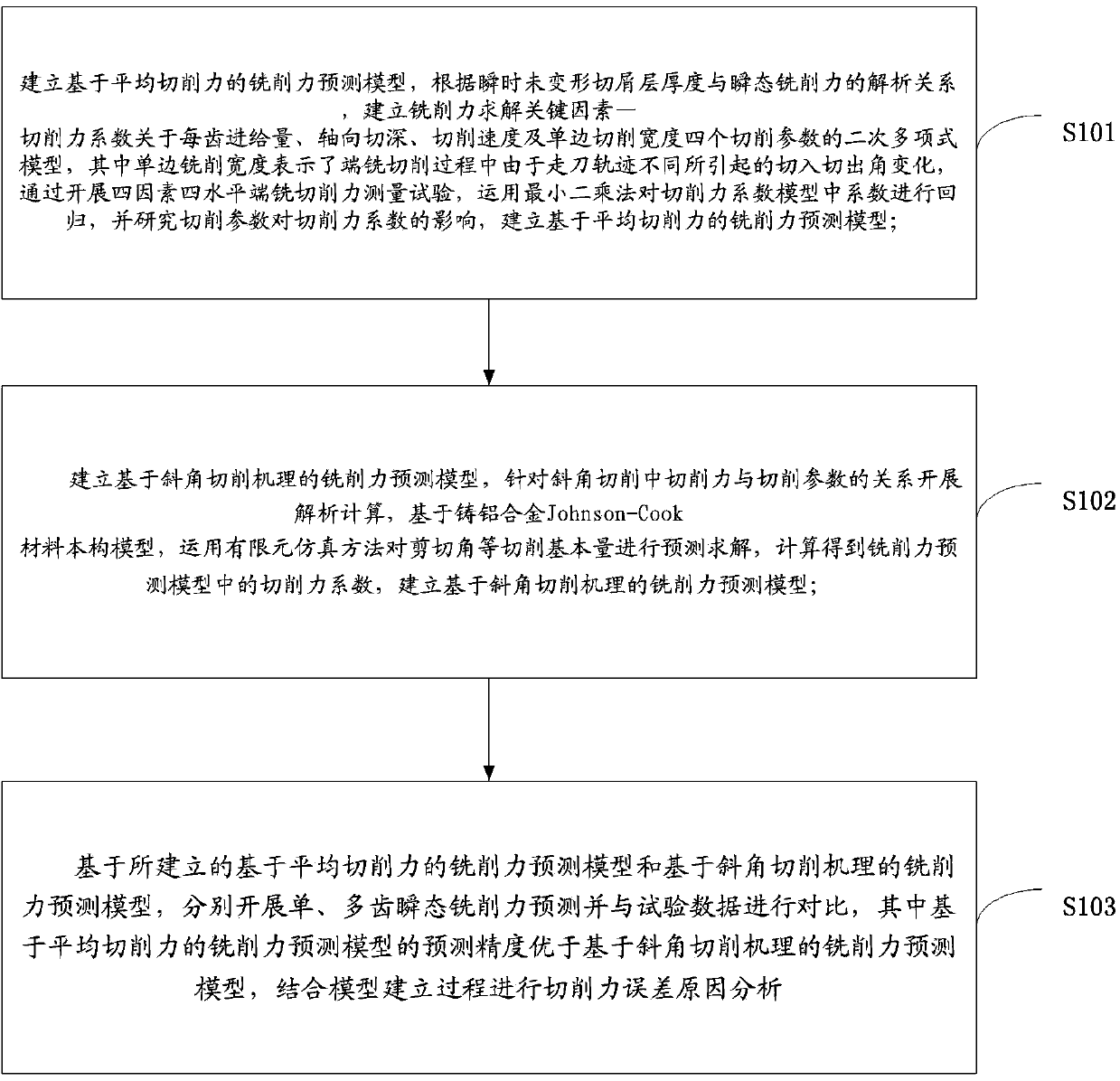
[0083] The present invention is achieved in this way, and the concrete steps of a kind of construction method of aluminum alloy material end milling cutting force model are as follows:

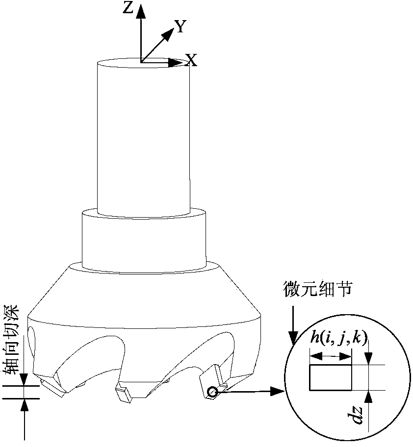
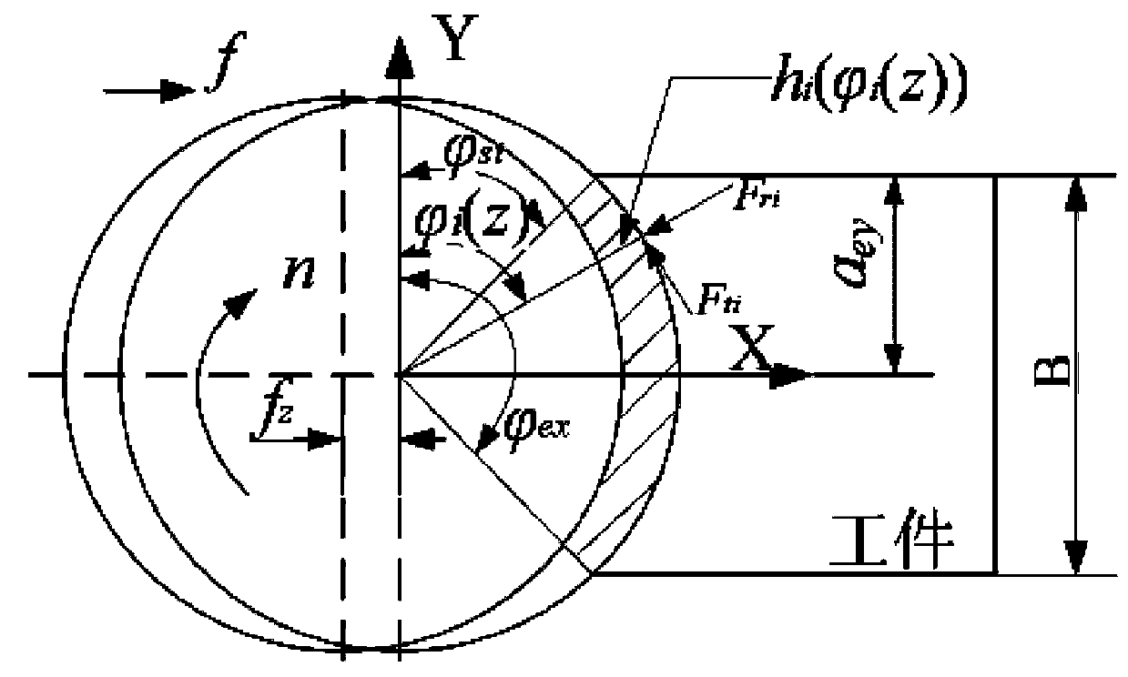
[0084] Step 1. Establish a milling force prediction model based on the average cutting force. According to the analytical relationship between the thickness of the instantaneous undeformed chip layer and the transient milling force, establish the key factor for solving the milling force—the cutting force coefficient on the feed rate per tooth, axial cutting force The quadratic polynomial model of the four cutting p...


PUM


Abstract

The invention discloses a construction method of an aluminium alloy material end milling-cutting force and cutting processing deformation model. According to the construction method, a milling-cutting force prediction model on the basis of an average cutting force is established; a milling-cutting force prediction model on the basis of an inclined cutting mechanism is established; on the basis of the established milling-cutting force prediction model on the basis of the average cutting force and the established milling-cutting force prediction model on the basis of the inclined cutting mechanism, single-tooth and multi-tooth transient milling-cutting force predictions are respectively carried out and obtained data is compared with testing data; an aluminum alloy material milling-cutting processing deformation model is established; on the basis of a real number encoded adaptive genetic algorithm, a flatness error of an end milled surface is predicted; the construction method has the important research significance for researching the processing deformation mechanism.

Description

technical field [0001] The invention belongs to the field of machining, and in particular relates to a method for constructing an aluminum alloy material end milling cutting force and cutting deformation model. Background technique [0002] At present, the research on the casting process of cast aluminum alloy materials at home and abroad has been relatively mature, but the research on the mechanical properties of different cast aluminum alloy materials is still limited to the study of static mechanical properties. The research on the dynamic mechanical properties of cast aluminum alloy materials has not yet been carried out. Therefore, it is of great significance to study the dynamic mechanical properties of cast aluminum alloy materials under high-speed cutting conditions for the study of machining deformation mechanism. [0003] According to the characteristics of cast aluminum alloy materials, the main processing method of cast aluminum alloy complex box parts is end mil...

Claims


Application Information

Patent Timeline
IPC IPC(8): G06F19/00
Inventor 焦黎王西彬钱钰博孙厚芳解丽静
Owner BEIJING INSTITUTE OF TECHNOLOGYGY
Learn More