
Debugging clamp of detector assembly

A detector assembly and fixture technology, which is applied to workpiece clamping devices, manufacturing tools, etc., can solve the problems of long debugging time and poor accuracy of detector assemblies, and achieve the requirements of three-dimensional direction debugging, high adaptability, and simplified debugging process. Effect

Active Publication Date: 2015-03-04
ACAD OF OPTO ELECTRONICS CHINESE ACAD OF SCI
View PDF4 Cites 4 Cited by
  • Summary
  • Abstract
  • Description
  • Claims
  • Application Information

AI Technical Summary

Problems solved by technology

[0005] The technical problem to be solved by the present invention is to provide a debugging fixture for a detector assembly, which can accurately and efficiently debug the detector assembly from a three-dimensional direction, thereby solving the problems of long debugging time and poor precision of the existing detector assembly

Method used


Image

  • Debugging clamp of detector assembly
  • Debugging clamp of detector assembly

Examples


Embodiment Construction

[0015] The following clearly and completely describes the technical solutions in the embodiments of the present invention. Obviously, the described embodiments are only some of the embodiments of the present invention, but not all of them. Based on the embodiments of the present invention, all other embodiments obtained by persons of ordinary skill in the art without making creative efforts belong to the protection scope of the present invention.

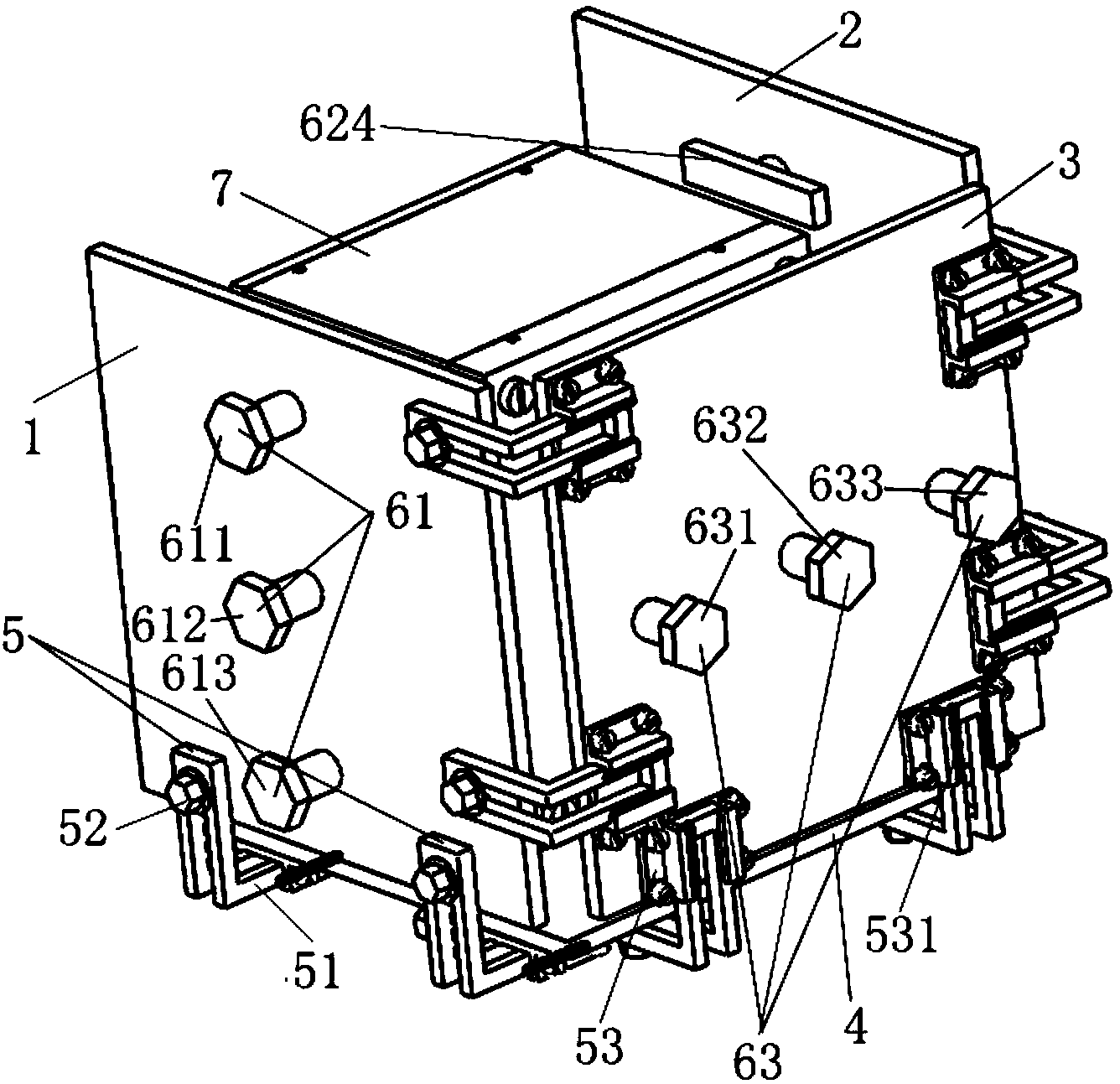
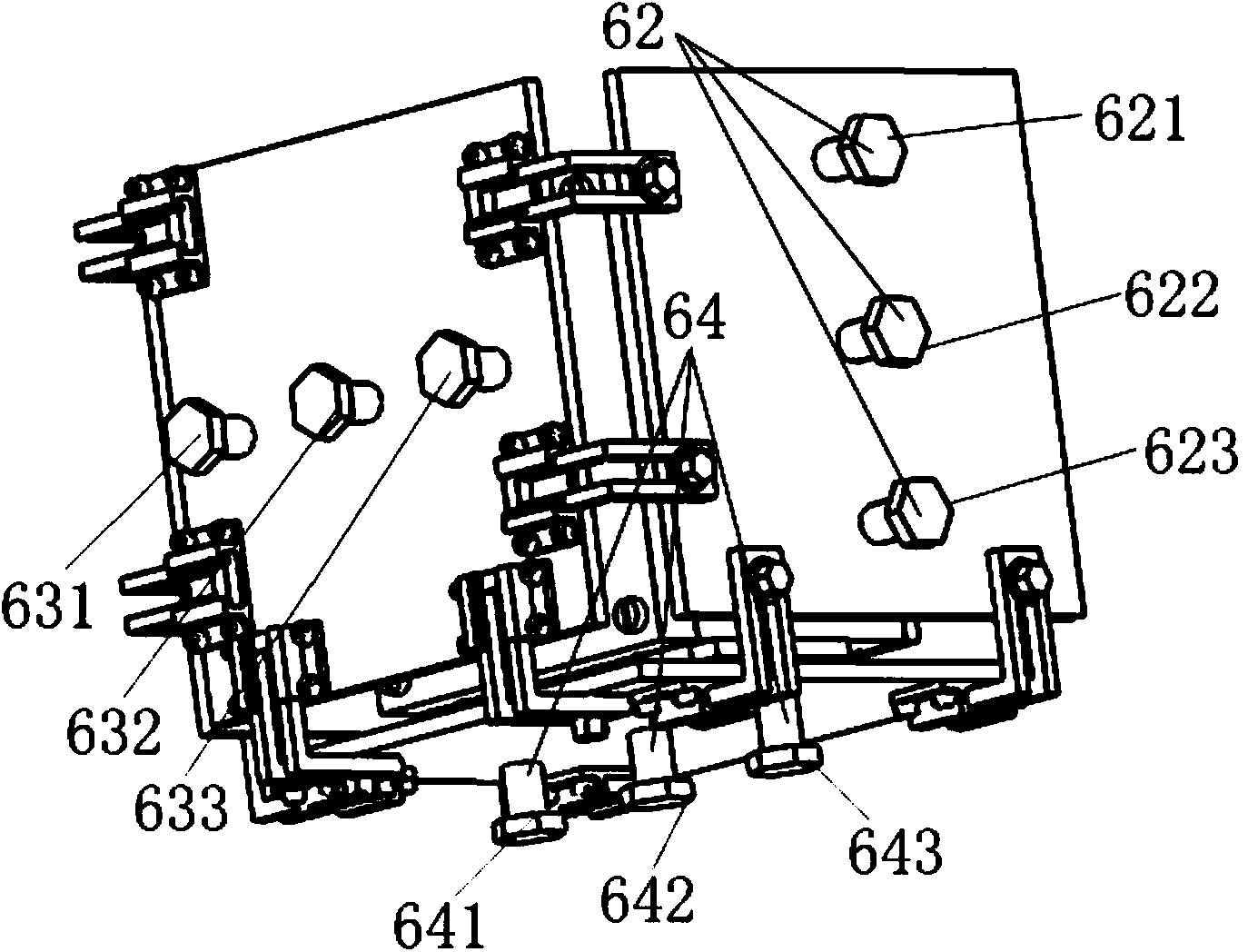
[0016] figure 1 , figure 2 Shown is a debugging fixture for a detector assembly provided by an embodiment of the present invention, which is used for debugging the detector assembly. The debugging fixture includes:

[0017] Four baffle plates 1, 2, 3, 4, several adjustable guide rail connection assemblies and several adjustment screw assemblies 61, 62, 63, 64; wherein,

[0018] One of the four baffles 1, 2, 3, and 4 is the bottom baffle 4, and the other three baffles 1, 2, and 3 are respectively arranged above the three sides of ...


PUM


Abstract

The invention discloses a debugging clamp of a detector assembly, and belongs to the field of debugging equipment of the detector assembly. The debugging clamp comprises four baffle plates, a plurality of adjusting type guide rail connecting assemblies and a plurality of adjusting screw assemblies, wherein one baffle plate of the four baffle plates is a bottom baffle plate, the other three baffle plates of the four baffle plates are respectively arranged above three edges of the bottom baffle plate and are all vertical to the bottom baffle plate, and debugging space which is used for placing a to-be-debugged detector assembly is defined by the four baffle plates; every two adjacent baffle plates of the four baffle plates are connected through at least one adjusting type guide rail connecting assembly, and the positions, which are relative to other baffle plates, of the each baffle plate can be adjusted by each baffle plate through the corresponding adjusting type guide rail connecting assembly which is connected with the corresponding baffle plate; each baffle plate is provided with at least one adjusting screw assembly, and an adjusting block arranged at the front end of each adjusting screw assembly is arranged in the debugging space.

Description

technical field [0001] The invention relates to the field of debugging of detector assemblies, in particular to a debugging fixture of a detector assembly which effectively reduces the difficulty of debugging the detector assembly and improves the debugging accuracy. Background technique [0002] With the progress of society and the continuous development of science and technology, the precision requirements for equipment are getting higher and higher. Although modern processing technology and precision have been improved enough, for equipment with high precision assembly and adjustment, the final design The realization is guaranteed by debugging, so the convenience and high efficiency of the installation and adjustment have become the objects sought after by the installation and adjustment personnel. [0003] According to the requirements of the design, in order to improve the accuracy and efficiency of the installation and adjustment, some corresponding installation and ad...

Claims


Application Information

Patent Timeline
Patent Type & Authority Applications(China)
IPC IPC(8): B25B11/00
CPCB25B11/00
Inventor 何晓英周锦松冯蕾付锡禄卜美侠
Owner ACAD OF OPTO ELECTRONICS CHINESE ACAD OF SCI
Learn More