
Clamping device

A kind of clamping equipment and clamping technology, applied in the direction of metal processing equipment, instruments, manufacturing tools, etc., can solve the problems affecting the repeatability of measurement, etc., and achieve the effect of high balance quality

Active Publication Date: 2015-02-25
SCHENCK ROTEC GMBH
View PDF8 Cites 0 Cited by
  • Summary
  • Abstract
  • Description
  • Claims
  • Application Information

AI Technical Summary

Problems solved by technology

But the concentricity error caused by this tolerance is reflected in the measurement result and seriously affects the repeatability of the measurement

Method used


Image

  • Clamping device

Examples


Embodiment Construction

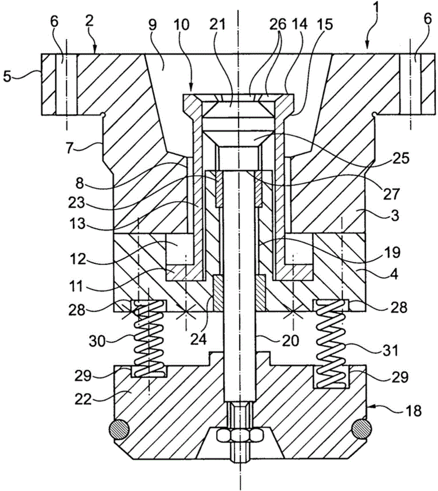
[0018] The illustrated clamping device 1 is inserted into the open end of the hollow main shaft of the balancing machine for this purpose. The clamping device 1 has a receiving unit 2 composed of two parts connected to each other by a screw connection, a receiving part 3 and a supporting part 4. A flange 5 with a fixing bore 6 on the receiving part 3 is used to fix the receiving unit 2 on the end face of the hollow spindle. In order to accurately center the hollow spindle, the receiving part 3 is provided with a centering surface 7 on its outer side. A through hole 8 extends axially through the accommodating part 3, which leads to a central accommodating opening 9, which is designed to accommodate a standardized hollow bevel clutch shaft of a tool. Of course, the accommodating part 3 can also be constructed, and the accommodating part 3 also has a differently designed accommodating opening for accommodating a clutch shaft of another shape.

[0019] In the through hole 8 there i...


PUM


Abstract

The invention relates to a clamping device (1) for clamping a tool holder for a drilling, milling or grinding tool in a balancing machine, the clamping device comprising a receiving unit (2) with a receiving opening (9) for the coupling shaft of the tool holder and a collet chuck (10). In said clamping device, the shaft (20) of an actuating unit (18) for actuating the collet chuck (10) is slidingly guided in a central bore (19) of the receiving unit (2). At one end, the shaft (20) has a force introduction body (22) on which a plurality of compression springs (30, 31) are supported, by means of which the collet chuck (10) can be tensioned. The compression springs (30, 31) are arranged and / or designed such that, when the collet chuck (10) is tensioned, spring forces acting on the force introduction body (22) load the force introduction body (22) asymmetrically relative to the axis of the shaft (20).

Description

Technical field [0001] The invention relates to a clamping device for clamping machine parts defined as rotating around an axis of rotation in a balancing machine, in particular a tool holder for drilling, milling or grinding tools. Background technique [0002] The above-mentioned types of clamping devices are mainly used for clamping tools that can be driven to rotate at a high speed in a balancing machine. Higher requirements are put forward for the balance of such tools, because tools that are not fully balanced can impair processing quality. In order to meet the higher requirements for balance quality, the precise center clamping of the tool to be balanced requires the aid of a clamping device arranged on the main shaft of the balancing machine. [0003] Known from WO 00 / 45983A1 is a clamping device for clamping a tool holder provided in a balancing machine, in which a base unit fixed on a machine spindle driven in rotation about a rotation axis has a centered relative to the...

Claims


Application Information

Patent Timeline
Patent Type & Authority Applications(China)
IPC IPC(8): B23B31/26G01M1/04
CPCG01M1/04B23B2260/136B23B31/265Y10T279/1008B23B31/26
Inventor A.布施贝克M.布莱特威泽D.皮特A.斯托克
Owner SCHENCK ROTEC GMBH
Learn More