Method and bearing for balancing rotors without journals

A technology of supporting devices and rotors, applied in static/dynamic balance testing, measuring devices, testing of machine/structural components, etc., can solve problems such as inaccurate measurement results

Inactive Publication Date: 2009-08-26
SCHENCK ROTEC GMBH
View PDF4 Cites 0 Cited by
  • Summary
  • Abstract
  • Description
  • Claims
  • Application Information

AI Technical Summary

Problems solved by technology

This can lead to less accurate measuring results, for example, in the event of end face runout errors (Planschlagfehlem)

Method used


Image

  • Method and bearing for balancing rotors without journals
  • Method and bearing for balancing rotors without journals
  • Method and bearing for balancing rotors without journals

Examples


Embodiment Construction

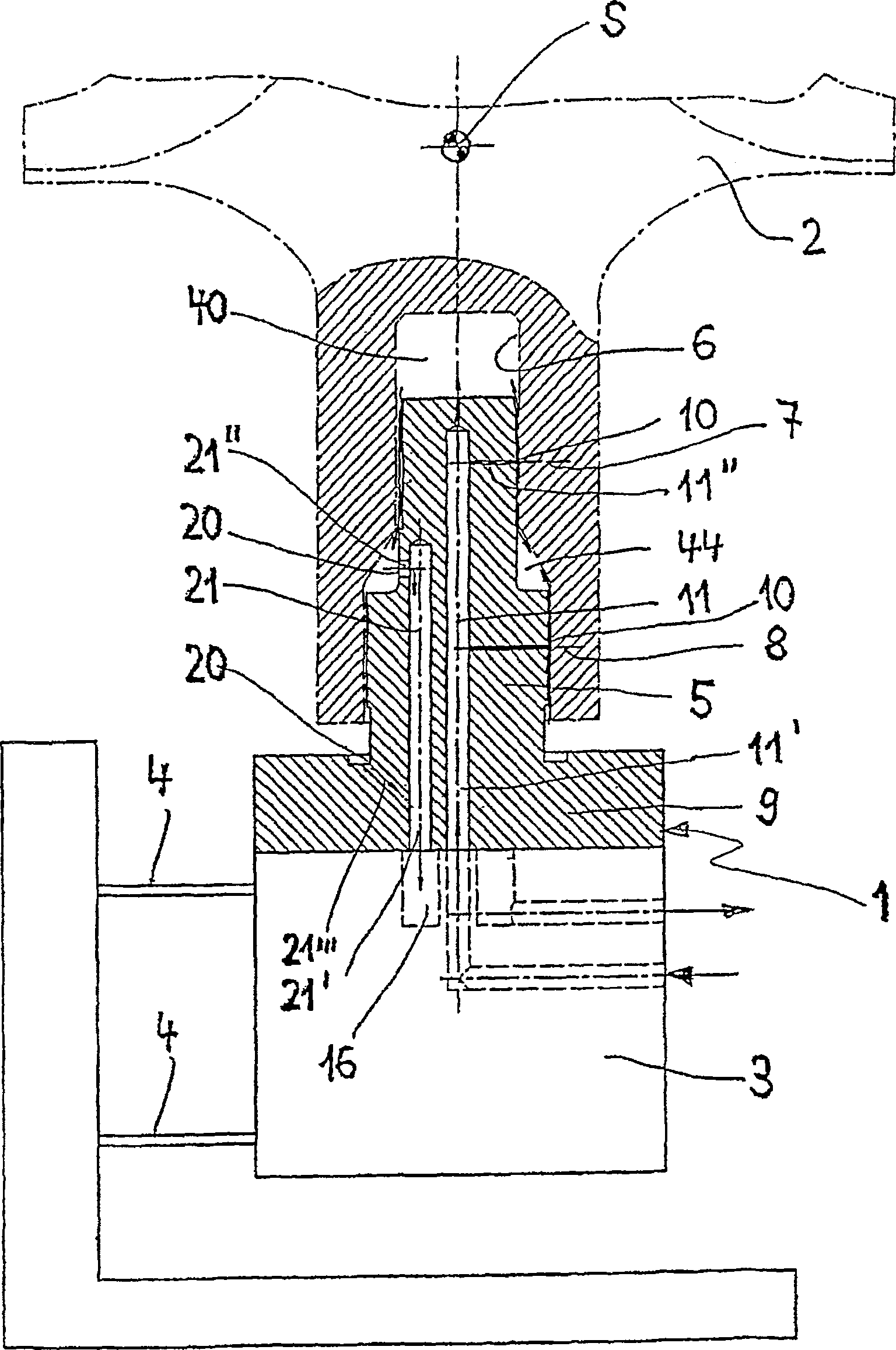
[0015] figure 1 Indicated for a rotor 2 to be checked (in figure 1 Indicated by dotted lines) the supporting device 1 is fixed on a balance bridge 3 of a balancing machine. The bearing device 1 has a bearing mandrel 5 on which the rotor 2 to be checked or balanced is rotatably mounted. The balancing bridge 3 is normally supported vibratingly on the balancing machine frame by means of, for example, four support springs 4, only two of which are shown in the figure. The rotor 2 is driven in rotation by a drive not shown further here. The unbalance-induced vibrations of the bearing spindle or balancing bridge 3 are measured and used to determine the degree of unbalance on the rotor 2 to be balanced.

[0016] The rotor 2 has a closed central rotor bore 6 , ie a blind bore, by means of which the bearing on the vertically arranged bearing mandrel 5 takes place. The center of gravity S of the rotor lies axially outside the length dimension of the blind bore, ie outside the bearing...


PUM


Abstract

In order to support a non-journaled rotor (2) with a hole (6) in a balancing machine by means of a supporting mandrel (5) with holes (10, 20) for fluid flow , to determine with high precision the unbalance of the rotor (2) with a blind hole, the invention proposes to supply a fluid chamber (40) formed between the end of the blind hole and the end of the support mandrel Inject fluid to form a fluid cushion that axially supports the rotor.

Description

technical field [0001] The invention relates to a method of balancing a journalless rotor and a support device for supporting a journalless rotor with a bore in a balancing machine by means of a support mandrel. Background technique [0002] A journaled rotor can be precisely balanced on the basis of the rotor bearing points provided on the journal. Rotors to be balanced, which do not have their own bearing points and which are clamped to the auxiliary shaft during balancing, present problems in achieving a certain balancing accuracy. [0003] A method is known from EP 0104266 A1 with which a journalless rotor can be balanced with high balancing accuracy without an auxiliary shaft. For this purpose, the rotor is mounted on the bearing mandrel of the balancing machine and a bearing fluid is introduced between the opposing rotor and mandrel surfaces. Errors due to surface inaccuracies no longer manifest as shape deviations in the rotor bore or support mandrel are rounded or ...

Claims


Application Information

Patent Timeline
Patent Type & Authority Patents(China)
IPC IPC(8): G01M1/04G01M1/16
CPCG01M1/04
Inventor 迪特尔·西伦
Owner SCHENCK ROTEC GMBH
Why Eureka
Try Eureka